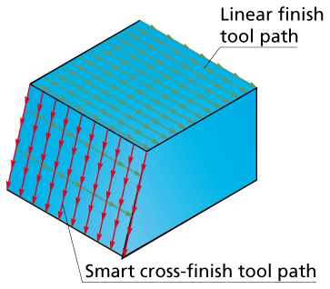
Linear Finish strategy
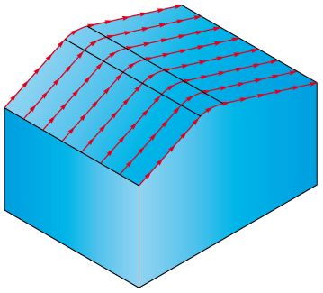
In linear cutting, the lines of a linear pattern are generated on a
2D plane above the model. The linear pattern is then projected on the
3D Model. During this projection, the Z-position of the tool is calculated
to avoid gouging of the material.
The Linear Finish dialog box displays the parameters of the Linear finishing.
Direction type
These options control the direction of the tool on each line of the linear pattern that has been projected on the model. Different materials and cutters require specific cutting conditions, e.g. some tools give better surface finish when cutting only downward; in other applications you need to use other settings to achieve optimum results.
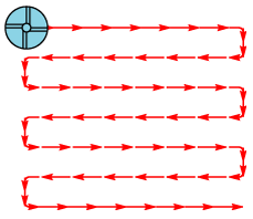
The tool finishes one line of the linear pattern and then directly moves to the next line, and so on. It mills forward and backward without leaving the material, thus constantly switching between climb and conventional milling.
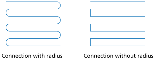
Connection radius: you can connect lines of the linear tool path with a radius. If the Radius value is 0, SolidCAM connects the linear tool path with straight lines.
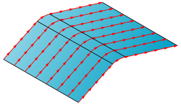
The tool finishes one line of the linear pattern. At the end of the line, the tool rapidly moves (G0) to the safety distance and then to the start of the next cut line. The tool always uses climb or conventional milling.
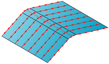
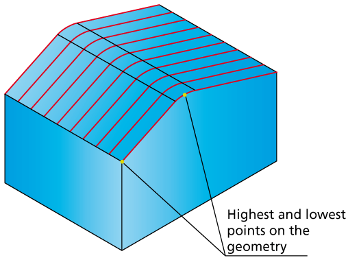
The tool always cuts from the lowest point of the tool path line to the highest point. From the highest point of the cut, the tool moves rapidly to the start point of the next cut.
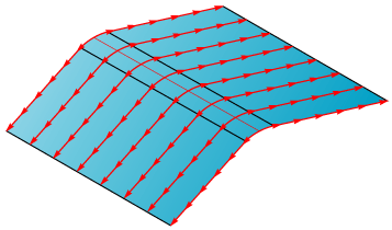
The tool always cuts from the highest point of the tool path line to the lowest point. From the lowest point of the cut, the tool moves rapidly to the start point of the next cut.
Value
Enter the angle value that defines the orientation of the tool path. The value of 0 generates the tool path lines in the direction of the positive X-axis.
Line
The Define button is available and you can define a line that determines the orientation of the tool path. The direction vector is defined by picking two points that define the start point and the end point of the direction line. The angle of the selected line is the output to the angle field.
Technology
In linear finishing, SolidCAM generates a line pattern on a 2D plane above the model and then projects it on the 3D model. The Step over value determines the constant distance between all lines of the linear pattern created on the 2D plane before it is projected.
This option enables you to control the distance between the tool path lines by the cusp height you want to achieve on the finished model. SolidCAM adjusts the distance between the single lines of the 2D pattern (before projection on the model) to the topology of the model to match the specified scallop height.
On flat areas, bull nose tool can achieve a small scallop with a rather large step over. You can use this value if you want to limit the chip load on the tool or the cutting forces that a large step over could cause.
You can create G2/G3 GCode output from Linear finish operations.
More...
Cross finish
Cross finish type
- None
Linear machining is performed only in the direction you have specified and no cross finish is executed.
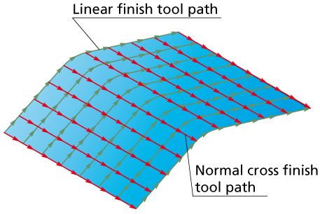
- Normal
After finishing the model in the first specified direction, another linear finish is performed at an angle of 90° to the first cutting direction. The complete area that has been machined in the first cut linear operation is machined again.
- Smart
The areas that have not been finished within the given scallop during the first linear finish operation at an angle of 90° to the first cut are machined again. The values of Maximum step over and Minimum step over affect the calculation. If the scallop can be achieved using side steps larger than the minimum step over, no cross finish is necessary - some other constellation could result in all the working area to be re-machined.
Minimum step over
This value can be used to avoid tool paths that are too narrow. You can, for example, enter a scallop of 0.02. For some areas SolidCAM would calculate a distance between two lines with 0.01 or less (at very steep walls). To reduce machining time and to avoid long GCode files, you can limit the minimum step over of the tool to 0.05.
Related Topics