Contour 5 -Axis Geometry
The Geometry section enables you to define the geometry for the Contour 5-Axis operation.
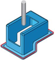
Drive curve
This section enables you to define the curve on which machining is performed. The tool is automatically offset with the tool radius. |
 |
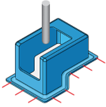
Orientation lines
This section enables you to define the lines that control the tool axis orientation along the drive curve. |
 |
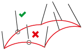
Maximum snap distance
This parameter defines the maximum distance between orientation line end points and the drive curve. When tilting is applied to a contour, only lines within this distance are used, while other lines that are far from the contour are ignored. |
|
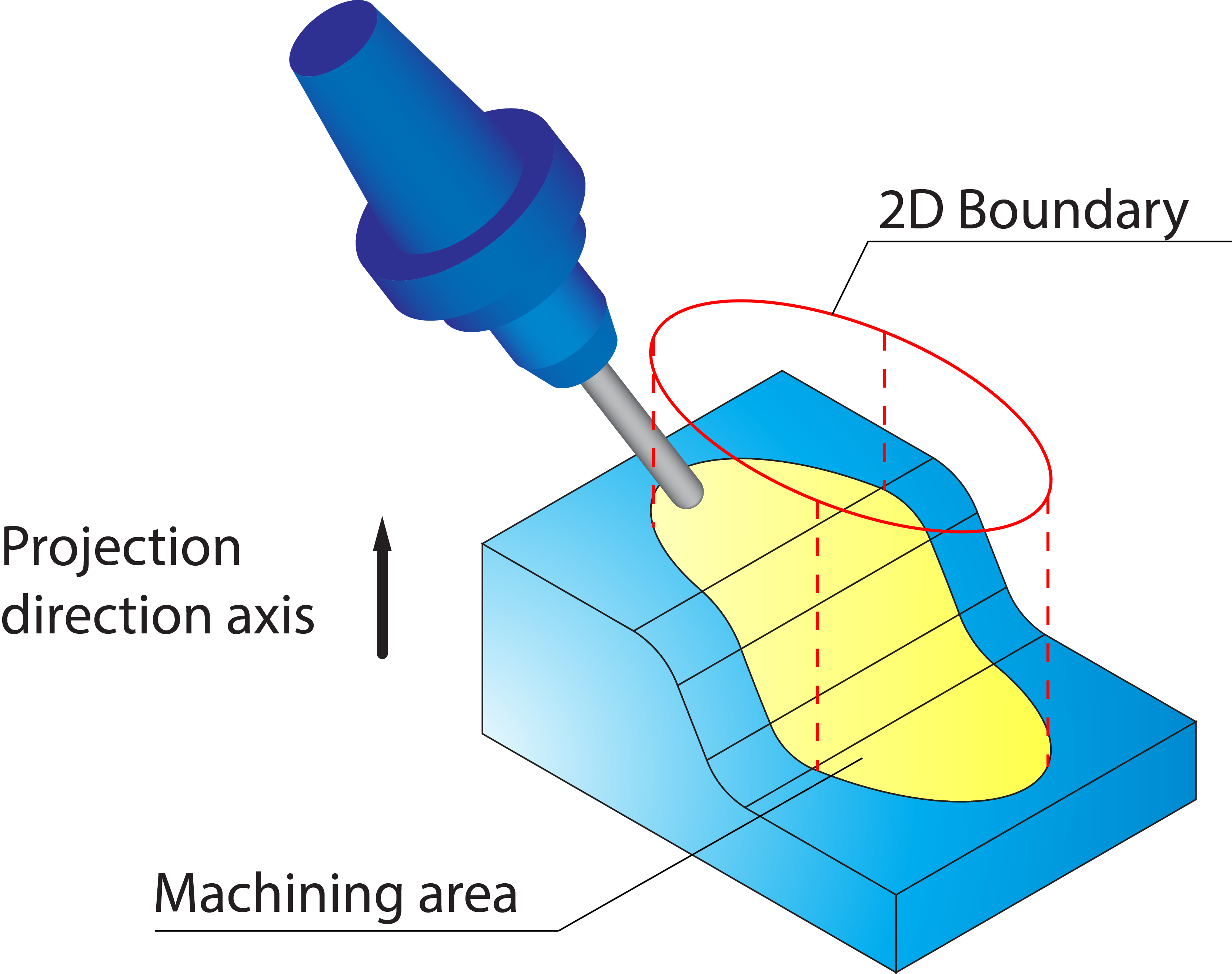
Use 2D Boundary
SolidCAM provides you with a functionality to limit the machining to specific model areas. The machining limitation is performed by a planar boundary that is projected on the model. The projected boundary is “virtually” trimming the drive surfaces. All the contact points of the tool and drive surfaces are enclosed by this projected boundary.
Click 2D Boundary. The 2D Boundary dialog box is displayed enabling you to define the boundaries.
2D Boundary curves
SolidCAM enables you to define a boundary based on a Working area geometry (closed loop of model edges as well as sketch entities).
Both ![]() and
and ![]() display the Geometry
Edit dialog box that enables you to define and edit the geometry.
display the Geometry
Edit dialog box that enables you to define and edit the geometry.
Show enables you to display the already defined boundary directly on the solid model.
Projection direction
When a planar boundary is defined, SolidCAM automatically projects the geometry onto the solid model. The direction of the projection is defined by a vector. SolidCAM enables you to choose an axis of the Coordinate System as a projection direction vector or define a vector by an end point (the start point is automatically considered to be located in the Coordinate System origin). |
 |