Levels
The Levels page enables you to define the machining levels.
Clearance
With this option, you can set clearance values.
The Use section allows you to choose one of the following geometries to define the clearance area:
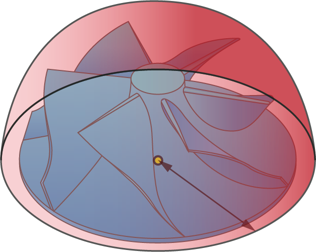
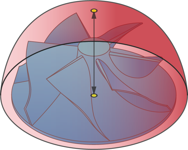
SphereWhen this option is chosen, the Clearance area has a spherical shape; it should enclose the multiblade part geometry completely. The tool performs a retraction movement to the Clearance sphere and then a rapid movement along the sphere surface. The axis of the sphere is always parallel to the rotary axis of the multiblade part. |
|
|
 |
|
 |
CylinderThis option enables you to define the Clearance as a cylindrical surface enclosing the multiblade part. The tool performs a retraction movement to the Clearance cylinder, and then a rapid movement along the cylinder surface. The axis of the cylinder is always parallel to the rotary axis of the multiblade part. |
|
|
 |
Auto detect dimension and position
In this option SolidCAM automatically defines the best fit sphere/cylinder radius and the best position of the sphere center of the multiblade part.
Levels
This section enables you to define the safety distance to approach and retract from the part.
Entry/Exit safety distance
After the descent movement to the Retract distance level, the tool starts the approach movement to the material. The approach movement consists of two segments. The first segment is performed with a rapid feed up to the Entry safety distance. From the Entry safety distance level, the approach movement is performed with the cutting feed. Upon retraction, the tool ascends to the Exit safety distance.