Technology
The Technology tab enables you to define the technological parameters of the Multiblade Machining operation.
|
This tab is not available in the Blade finishing technology when using the SWARF strategy. |
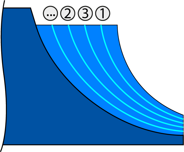
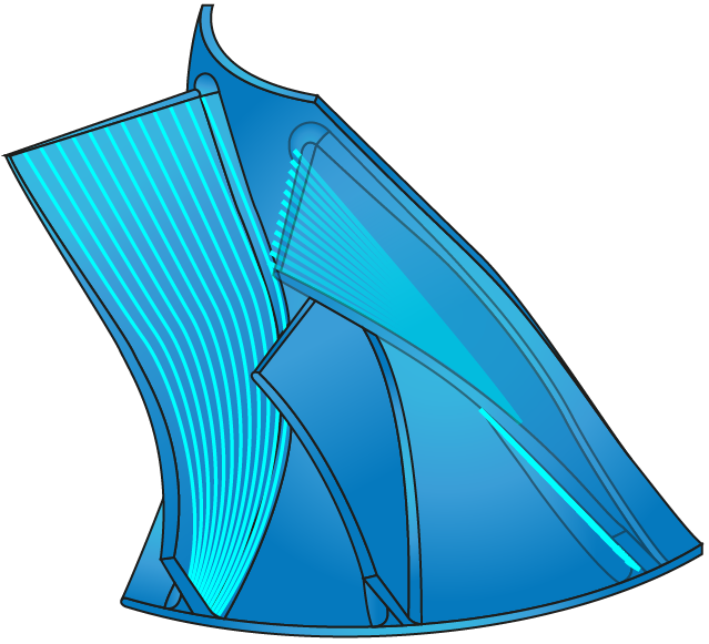
Layers
The layers are different depth levels of the roughing pattern. They are positioned on top of each other. The layers consist of the slices and can only be set if the technology is defined as Roughing or Blade finishing. The number of layers can be determined using one of two options:
This option sets the maximum number of layers for roughing. |
 |
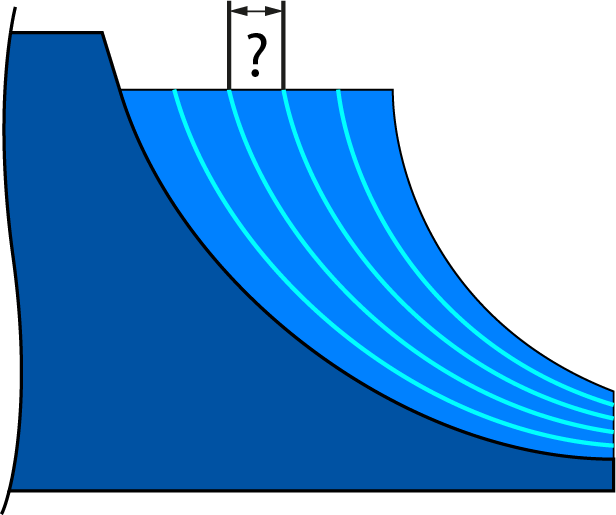
This option sets the maximum distance between two layers for roughing. |
 |
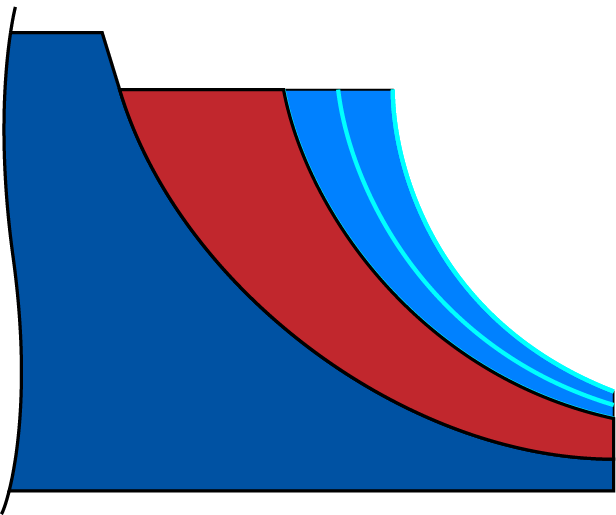
Rest material
In the Roughing technology, this option enables you to machine the areas in which the stock is left out by previous operations.
If some material is left for machining, this option enables you to machine the entire layer and not only the portion where the material remains. |
 |
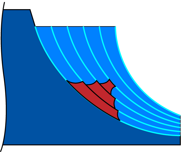
This option creates a tool path for the entire area of the blade considering only the height of the remaining stock. The width of the stock is not considered.
|
 |
|
The Rest Material option is available only when the Advanced check box is selected. |
Area
This option enables you to limit the area using a start distance from either the hub or the shroud. The area value must be entered as a percentage of the height of the blade.
This option enables you to determine a margin at the starting edge of the surface to avoid the inaccuracies of the surface edge and get a smooth cut. |
 |
This option enables you to determine a margin at the end edge of the surface to avoid the inaccuracies of the surface edge and get a smooth cut. |
 |
|
This option is available in the Roughing and Blade finishing technologies when using the Morph between Hub and Shroud strategy, when the Advanced check box is selected. |
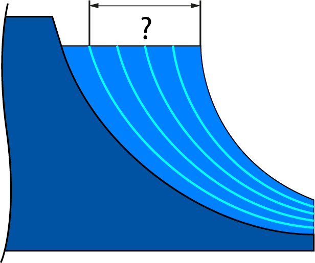
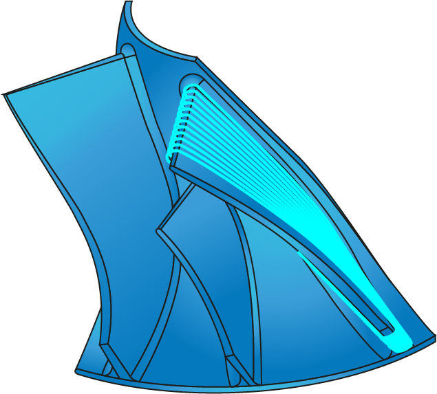
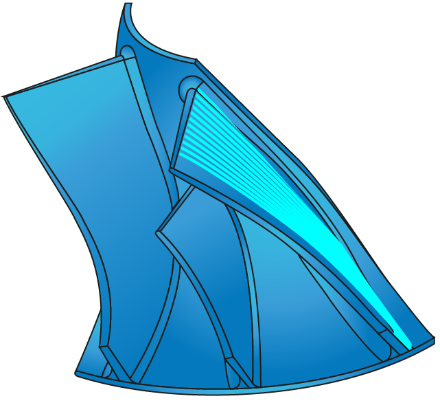
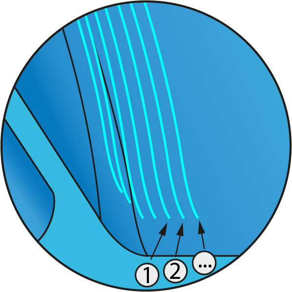
Slices
This option enables you to form the layer for Roughing and the pattern for the Hub finishing technology.
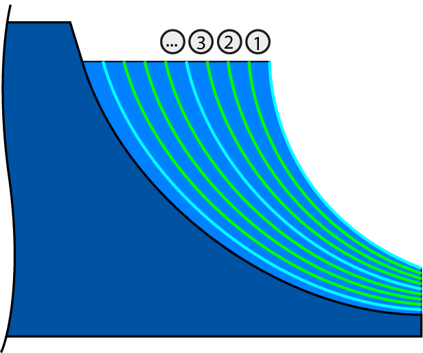
This option sets the maximum number of slices for roughing. |
 |
This option sets the maximum distance between two slices for roughing. |
 |
|
This option is available only in the Roughing and Hub finishing technologies. |
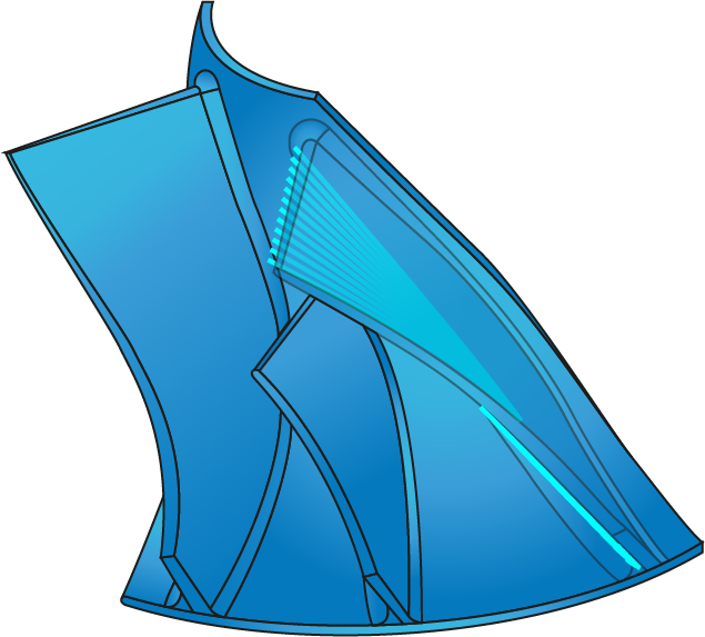
First slice
This option controls the first slot cuts where the tool is fully engaged.
This option creates multiple depth cuts on the first slice. |
 |
||
This option allows you to set a value that adds the first cut with the specified step down value to reduce the stress on the tool when slot cutting.
|
|||
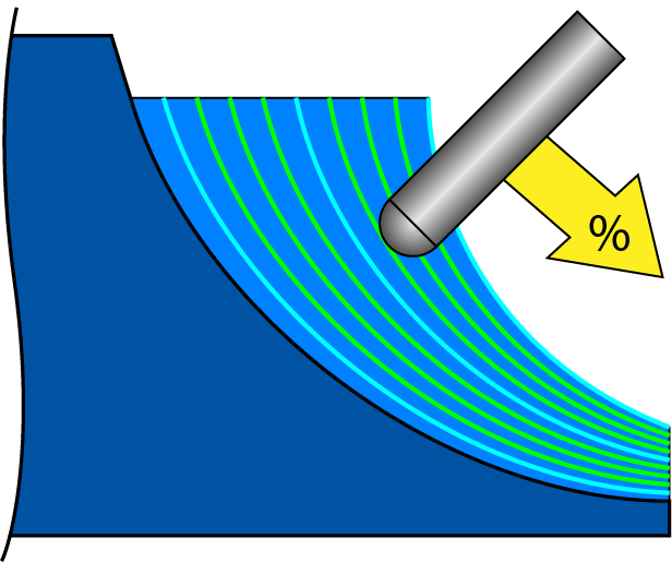
This option enables you to reduce the feed rate of the first slices to a percentage of the machining feed rate. |
 |
|
This option is available only in the Roughing and Hub Finishing technology, when the Advanced check box is selected. |
Contour
This option sets the area to machine the blade and the fillet.
This option enables you to activate a tool path created as a full contour around the blade. |
 |
In this option, the tool does not roll around the trailing edge. |
 |
In this option, the tool does not roll around the leading and trailing edge. |
 |
In this option, the tool path is created only on the left side of the blade. |
 |
In this option, the tool path is created only on the right side of the blade. |
 |
In this option, the tool path is created on the right side of the left blade and on the left side of the right blade. |
 |
|
The Contour option is available only in the Blade finishing and Fillet finishing technologies. The Pocket parameter is not available in the Fillet finishing technology.
|
Final cuts
When the Technology is selected as Roughing, this section enables you add additional cuts along the wall surface. This helps in improving the wall surface quality.
You can set the Number of final cuts and Final cuts stepover values in the respective fields.
The final cuts feed rate % allows you to set the feed rate on the final passes.
Blade side
This section enables you to define how the blade side is machined.
Area
This parameter defines the method of cutting.
This option sets the Number of cuts to machine the area. |
 |
In this option, a sphere of a specific diameter is rolled along the fillet to determine the two contact points to define the area to be machined. The Blade overlap parameter enables you to set the values for blade overlap. |
 |
This parameter uses the values defined in Hub side. |
Hub side
This section enables you to define how the hub side is machined.
Area
This parameter defines the method of cutting.
This option sets the number of cuts to machine the area. |
In this option, a sphere of a specific diameter is rolled along the fillet to determine the two contact points to define the area to be machined. The Hub overlap parameter enables you to set the values for hub overlap. |
This parameter uses the values defined in Blade side. |
By maximum number
This option defines the maximum number of cuts for finishing operation.
By maximum distance
This option defines the maximum distance between two passes of the tool path for finishing operation.
Both sides
Big tool diameter
In this option, SolidCAM rolls a sphere of a specified diameter along the fillet to determine the two contact points to define the area to be machined.
Side step
This option allows you to define the distance between two subsequent passes of the tool path.
|
The Blade side, Hub side, and Both sides options are available only in the Fillet finishing technology. |