Geometry
Strategy
The Strategy section enables you to define the strategy of the SWARF Machining. SolidCAM offers you the following strategies:
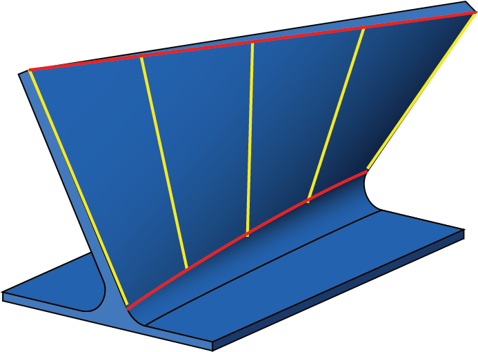
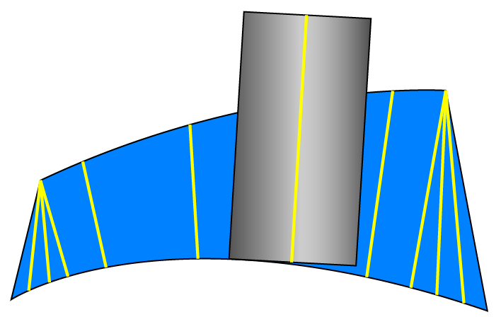
Synchronize with tilt linesThis strategy enables you to perform machining, while the tool axis is aligned to the Tilt lines along the Upper curve and Lower curve. SolidCAM automatically interpolates the tool axis between the tilt lines. Since this strategy provides manual control over the lead and lag angles, it can be used when all other strategies fail. |
 |
||
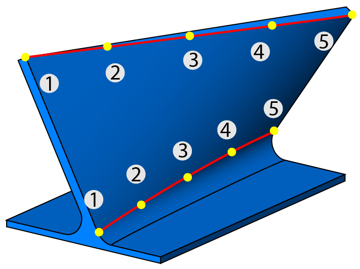
Synchronize with (upper/lower) curvesThis strategy enables you to divide the tool path along the Upper and Lower curves into equidistant length steps. Then the tool axis is aligned to each pair of steps.
|
 |
||
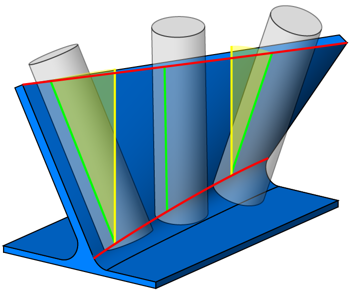
Synchronize with main directionThis strategy enables you to generate a tool path with a tool axis located as close as possible to the direction defined by one of the axes or by a line. In this case, the tool mainly tilts away to the side, while tilting around the axis is minimized. |
 |
||
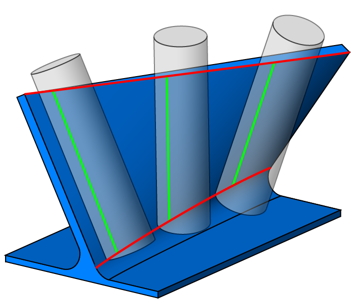
AutomaticThis strategy enables you place the tool onto a swarf surface in such a way as to achieve a line contact between the tool and surface.
The tool tilts only to the side, but always sticks to the main direction in one orientation.
|
 |
||
Shortest distanceThis strategy enables you to align the tool with the Upper and Lower curves by using the shortest distance between these two curves. |
 |
||
Normal to guide curveThis strategy enables you to drive the tool normal to the guide curve according to the defined curve and surfaces. All the edges are automatically extracted from the selected part surfaces. The option of Tilt lines is not available for selection with this option.
|
 |
||
Synchronize with ISO curvesThe strategy is designed to follow the ISO curves of a nurbs surface. |
 |
Part definition
Depending on the strategy chosen, the following geometries can be defined:
Swarf surfacesThis section enables you to define the surfaces where the machining will be performed in the Automatic strategy. |
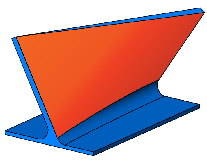 |
Floor surfacesThis section enables you to define the Floor surfaces that will be avoided during the machining. |
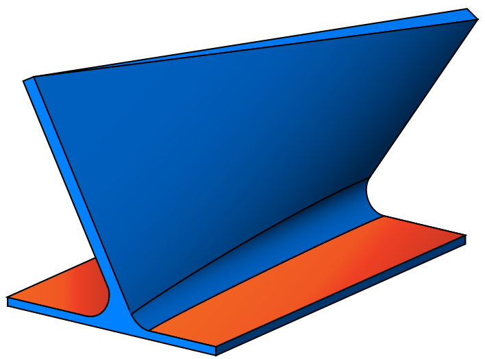 |
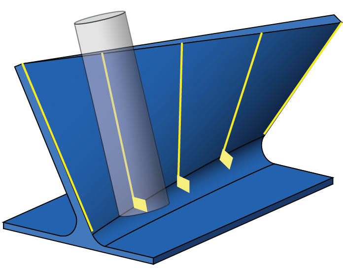
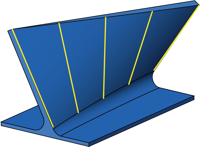
Tilt lines This section enables you to select the lines where the machining should start in the Synchronize with tilt lines strategy. |
 |
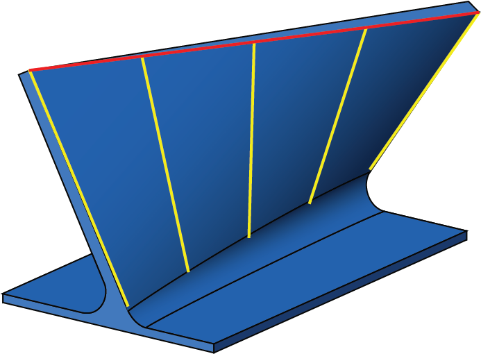
Upper curveThis section enables you to define the upper contact point of the tool. It should be the upper edge of the Swarf surface. |
 |
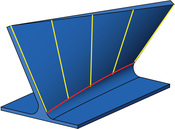
Lower curveThis section enables you to define the lower contact point of the tool. It should be the lower edge of the Swarf surface. |
 |
Offset
Swarf offset
The Swarf offset field enables you to define the value for the stock to leave on the surfaces.
Floor clearance
The Floor clearance field enables you to define the offset for the Floor surfaces. The tool can be compensated to an existing floor surface by projecting the tool along the tool axis until it reaches the floor. The machining is performed at the specified distance from the Floor surfaces.
A floor surface must be selected as the geometry. This option is available only when the Floor surfaces check box is selected in the Part definition section.
Drop tool to floor
When there is a gap between the machining surface and the floor surface the tool completely retracts or follows the floor surface. You can select between the options of Drop and retract and Retract only.
|
This option is available only when the Floor surfaces check box is selected in the Part definition section. |