Misc. parameters
The Misc. parameters page enables you to define a number of miscellaneous parameters and options related to the 5-axis tool path calculation.
Message
The Message field enables you to type a message that will appear in the generated GCode file.
Extra parameters
This Extra parameters table displays the list of additional parameters defined in the post-processor of the current CAM-Part.
Flyout Window
If you prefer working with a larger window, the Flyout Window option displays the Operation Option window.
Tool Center based Calculation
This option enables you to perform the tool path calculation based on the tool center.
The illustrations show the use of the Tool Center based Calculation option for Constant-Z machining.
When the option is turned off, the contact points between the tool and machined surface are located at the specified Z-levels. |
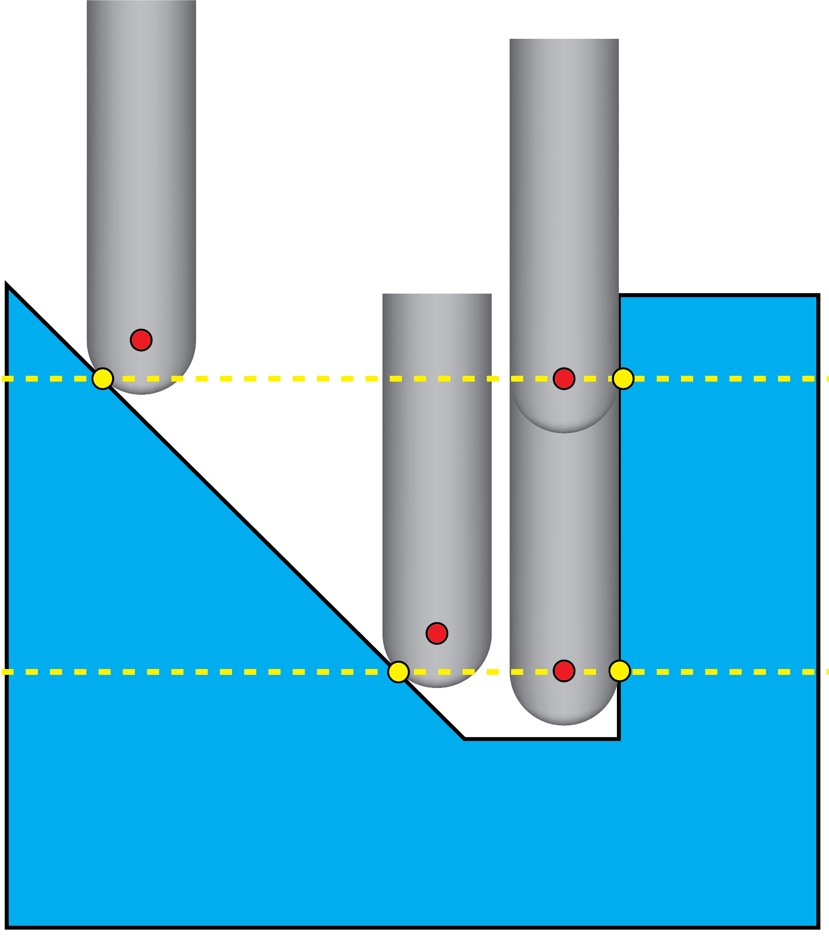 |
When the Tool Center based Calculation check box is selected, the tool center points are located at the specified Z-levels. |
 |
Smooth surface normals
SolidCAM enables you to smooth the drive surface normals.
Smoothing threshold
This parameter defines the limit of the surface normal angular variation. If the drive surface slice along the surface normal exceeds the specified value per distance unit (inch or mm), SolidCAM automatically defines a new surface normal for this segment, which is calculated using a linear interpolation from the surface normals at the start and end segment points.
Max. angle step for rotations axis
SolidCAM enables you to limit the rotary/tilt angle of the machine head.
Angle
This parameter defines the maximum angle step for the rotation/tilting axis, measured from the last tool path point. When the specified angle is smaller than the rotary/tilt angle kinematics of the machine, the distance between two tool path points is filled with additional points. The number of points is calculated by the division of the rotary/tilt angle and the maximum angle step, which results in an angular change consisting of small steps.
Custom triangulation
The Custom triangulation option enables you to achieve higher rate of accurate triangulation.
When the Custom triangulation check box is not selected, SolidCAM uses the native CAD triangulation method. When the Custom triangulation check box is selected, 5-Axis triangulation method is used to define the Triangulation tolerance and Max. edge length.
Max Edge Length
When the Max. edge length check box is not selected, the 5-Axis triangulation method is used, however, the results achieved are similar to the native CAD triangulation results. When the Max. edge length check box is selected, it allows you to control the maximum edge length of the triangle thereby increasing the amount of triangles on the given surface for a better definition of the surface.