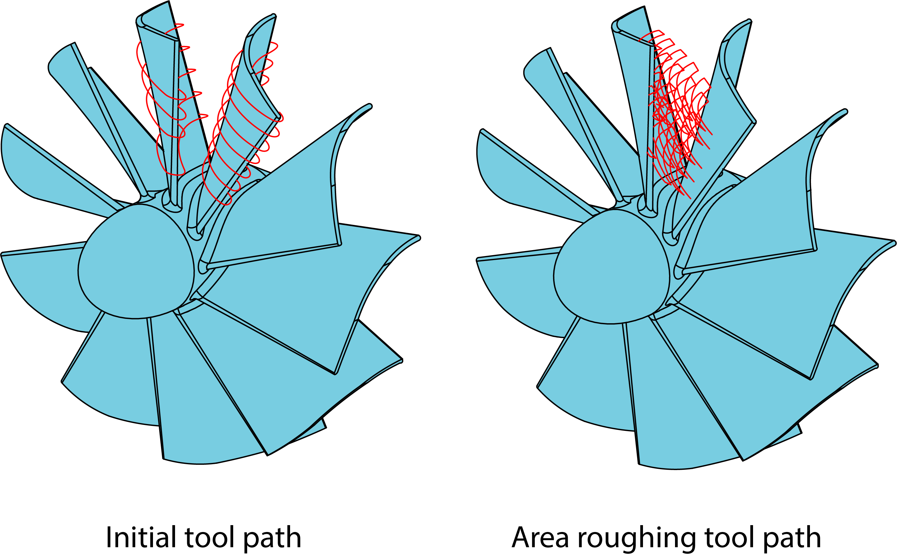
Area roughing
In this strategy, the roughing tool path is created inside the initial tool path. For example, the floor area between impeller blades can be machined using this strategy if the initial tool path describes the left and right side of the area limitations.
The Area roughing dialog box is displayed enabling you to define the parameters of the area roughing.
|
This option is available only in the Advanced mode. |
Use Area Roughing
Rotary axis around
This parameter defines the rotary axis. SolidCAM enables you to choose an axis of the Coordinate System (X, Y, Z) or define a rotary axis vector by an end point (the start point is automatically considered to be in the Coordinate System origin).
Rotary axis base point
With this option, SolidCAM enables you to define the position of the rotary axis directly on the solid model using Select point button.
Maximum step over
SolidCAM enables you to define a number of cuts either by the Maximum step over parameter (the distance between two successive cutting passes) or by the Number of cuts per section parameter.
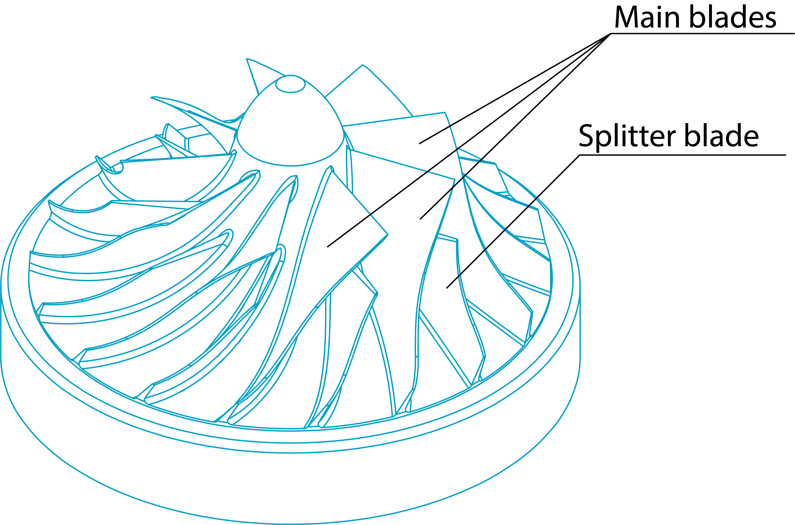
Area
SolidCAM enables you to machine the area enclosed between two main blades and containing a splitter blade. The Area option enables you to define the area where the machining will be performed.
Complete- The machining is performed in the complete area between the two main blades. Left side- The machining is performed in the area between the left main blade and the splitter blade. Right side- The machining is performed in the area between the right main blade and the splitter blade. |
 |
Cutting method
The Cutting method options enable you to define the passes direction and the way how the single passes will be connected into a complete tool path.
One way (along rotary axis)- With this option, the machining of the pass starts at the upper edge of the impeller floor face, continues along the blades and stops at the lower edge of the floor. Then the tool retracts to the start position of the next cutting pass.
One way (along reversed rotary axis)- With this option, the machining of the pass starts at the lower edge of the impeller floor face, continues along the blades and stops at the upper edge of the floor. Then the tool retracts to the start position of the next cutting pass.
Zigzag- With this option, the machining starts at the edge of the impeller floor face, continues along the blades to the other edge, steps over to the next cut at the same edge and continues machining to the first edge. The sequence for the cuts is from the left to the right.
Zigzag (climb only)- With this option, the machining begins in the center of the surface and progresses outwards to the sides.
Alternate direction to reduce path length- With this option, SolidCAM changes the start position of the cut in order to minimize air cuts.
|
This option is available only when the Zigzag (climb only) cutting method is chosen. |
Calculation applied
With this option, SolidCAM enables you to define when the calculation of the area roughing is performed. The area roughing calculation can be performed either before the tilting calculation (the Before tilting option) or after the collision control (the After collisions control option). If the area roughing calculation is performed after the collision control, the resulting tool path is checked again for collisions.
|
|
Calculation is applied Before tilting |
Calculation is applied After collision control |
When the After collisions control option is used, SolidCAM enables you to extend the tool path using Extension at start and Extension at end parameters.
Smoothing above splitter
With this option, SolidCAM enables you to create a morphed tool path in the area above the splitter. This smoothing is used for finishing operation.
|
This option is available only if After collision control is selected in Calculation applied. |
Trim cuts
This parameter enables you to define the cut length of the cuts.
By % of cut length- This option enables you to determine the percentage of the tool path length that must be trimmed.
When curvature exceeds tool diameter- This option enables you to trim the tool path while it is moving around the upper radius of the blade, when curvature of the blade gets bigger than the tool radius.
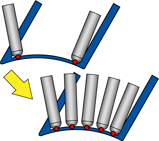
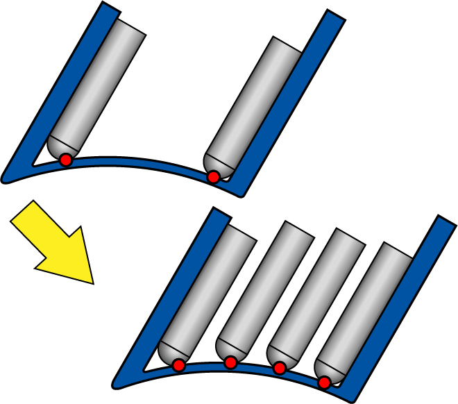
Depth cuts
This option enables you to copy the tool path pattern into tool contact line direction. This option generates a collision-free tool path pattern and upper cuts.
Number- This parameter defines the number of total cuts.
Spacing- This parameter defines the number of depth cuts for area roughing.
Start height- This parameter defines the start distance from tool path and depth cuts to their original position.

These options are available only if After collision control and Depth cuts are selected.