Tilted from curve away
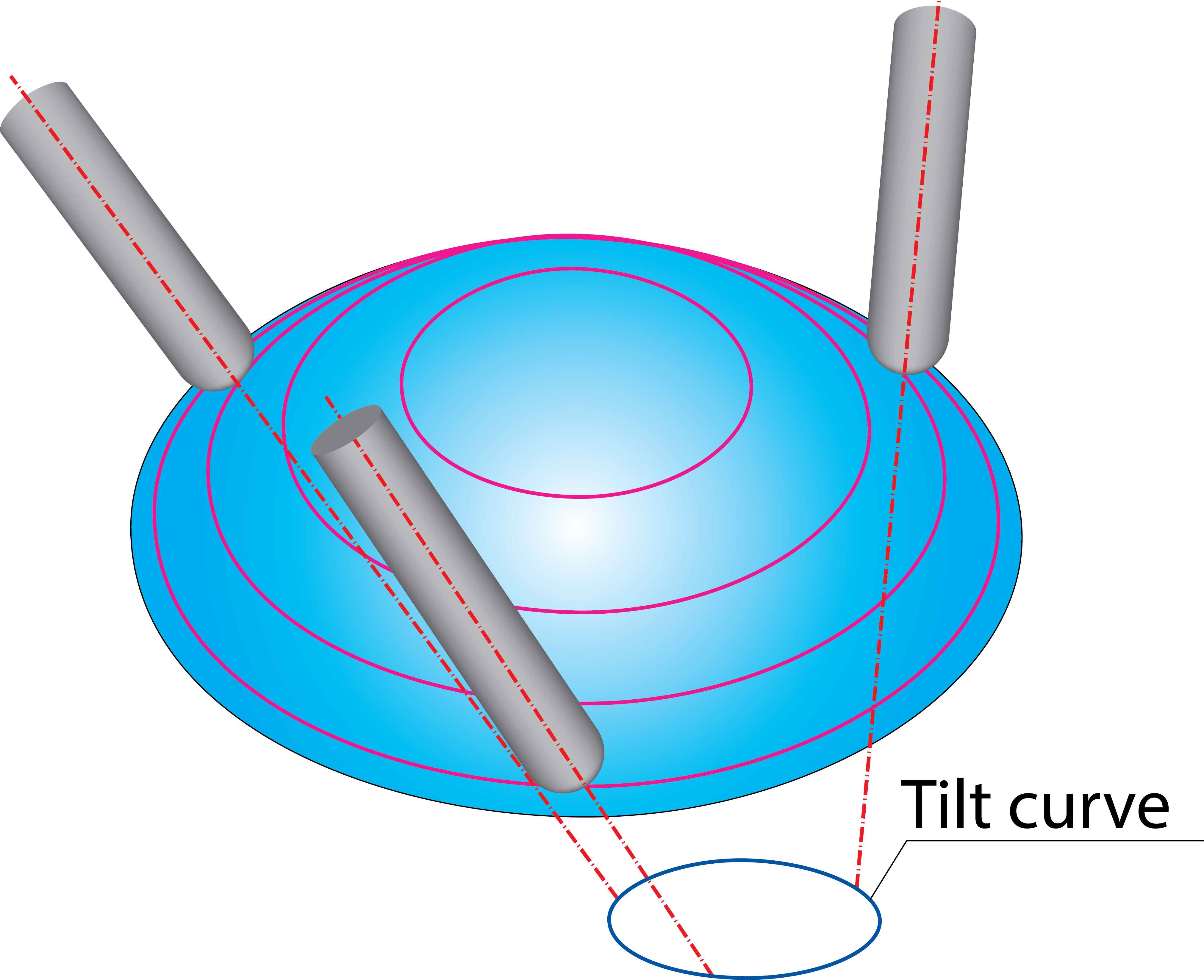
With this option, the tool axis intersects with the specified Tilt curve, similar to the Tilted through curve option. The tool axis coincides with the vector directed from the point on the Tilt curve to the tool contact point.
The tilt curve has to be located under the drive surface. The Tilt Curve section enables you to choose the existing profile
geometry for the tilt curve or define a new one with |
 |
Curve tilt type
The Curve tilt type options enable you to define the way how the start point of the tool axis vector is found on the Tilt curve. In other words, these options define how the tool axis is aligned relative to the Tilt curve.
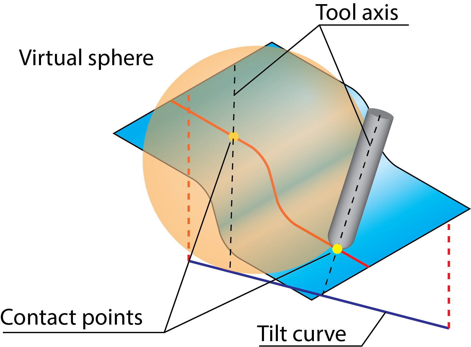
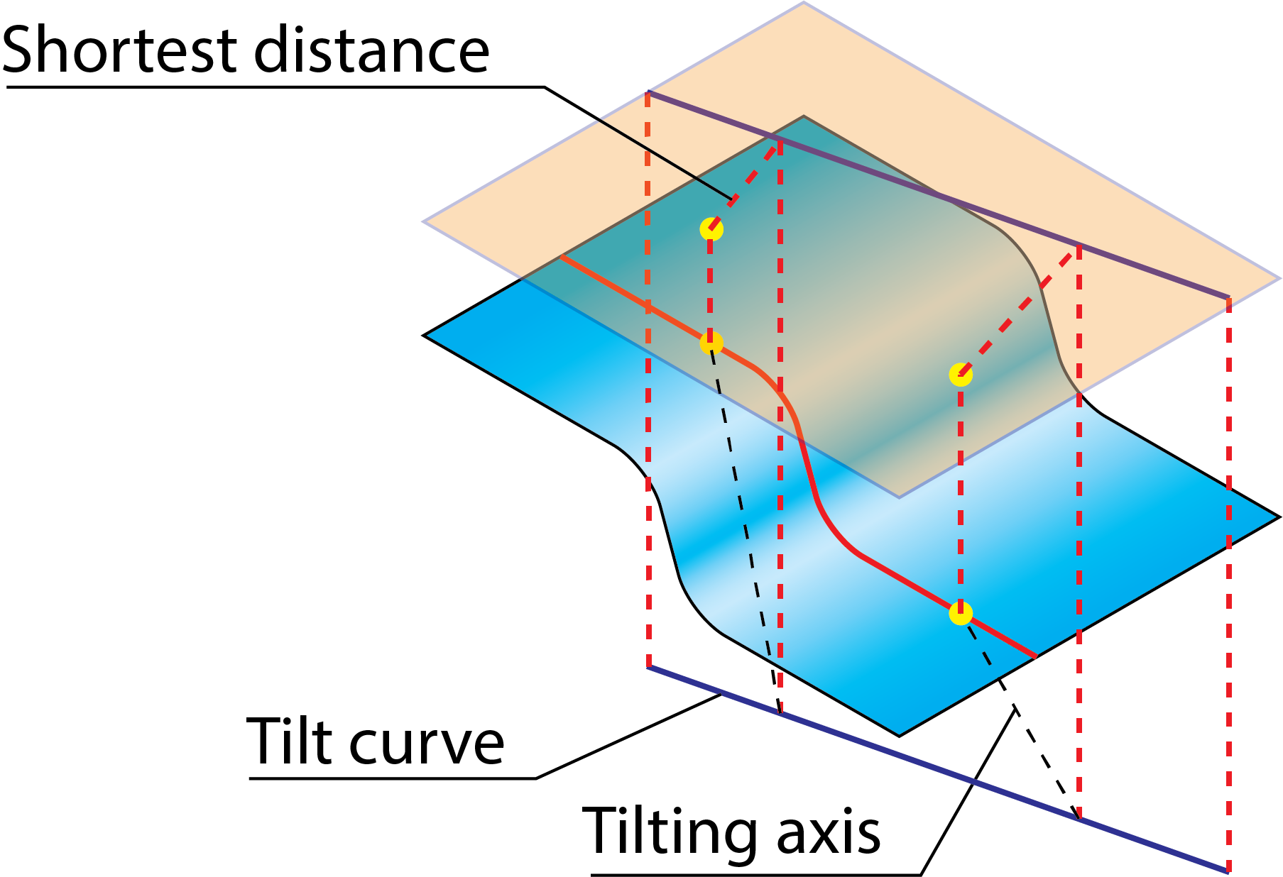
Closest pointThe tool axis is defined by direction vector connecting the contact point and the Tilt curve by the shortest distance. With this method, SolidCAM expands a virtual sphere from the contact point. The first intersection point between the sphere and the Tilt curve defines the shortest distance. |
 |
Angle from curveThe direction of the tool axis is determined using the projections of contact points and the Tilt curve on a plane orthogonal to the main spindle direction. On the illustration, the tool contact points and the Tilt curve are projected onto a plane parallel to XY-plane (the main spindle direction is the Z-axis). |
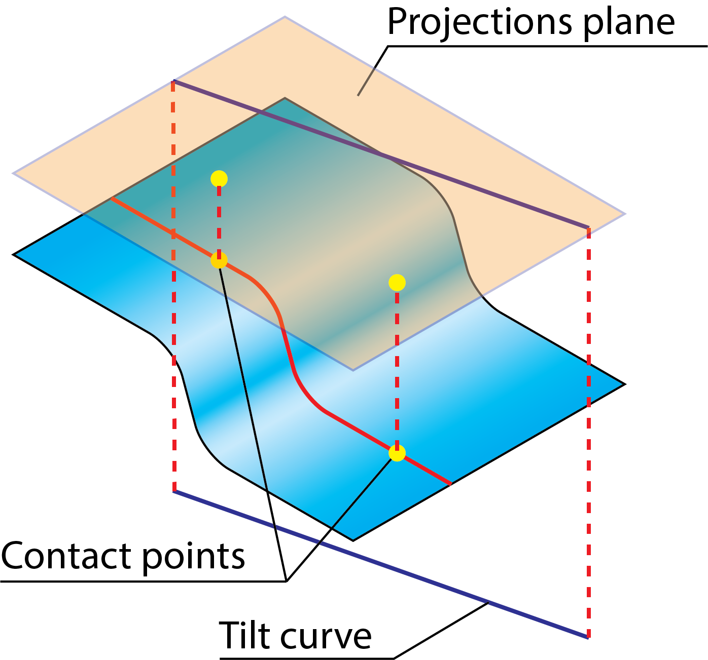 |
The projected contact points and the projection of the Tilt curve are connected by the shortest distance. The connecting points found on the projection are projected back onto the Tilt curve determining the direction of the tool axis. |
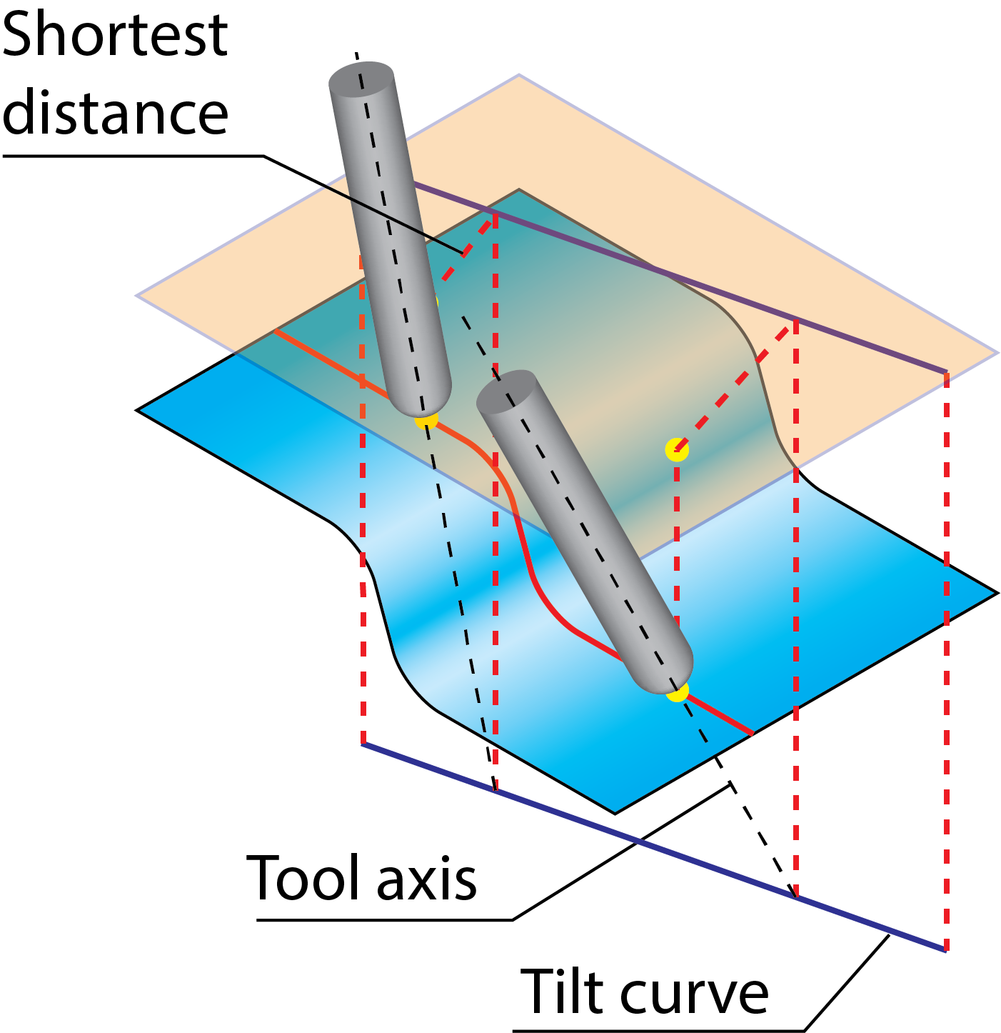 |
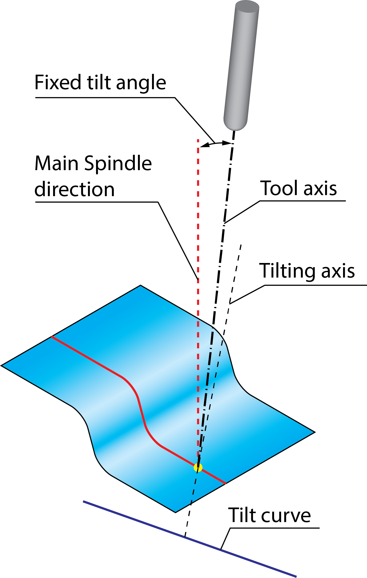
Angle from spindle, main directionThe tilting is performed from the main spindle axis at the specified Fixed tilt angle value towards the tilting axis. The orientation of tilting axis is determined using the projections of contact points and the Tilt curve on a plane orthogonal to the main spindle direction (see the Angle from curve option). On the illustration, the tool contact points and the Tilt curve are projected onto a plane parallel to XY-plane (the main spindle direction is the Z-axis). |
|
The projected contact points and the projection of the Tilt curve are connected by the shortest distance. The connecting points found on the projection are projected back onto the Tilt curve determining the direction of the tilting axis. |
 |
The tool tilting is performed from the main spindle direction towards the defined tilting axis at the specified Fixed tilt angle value. |
 |
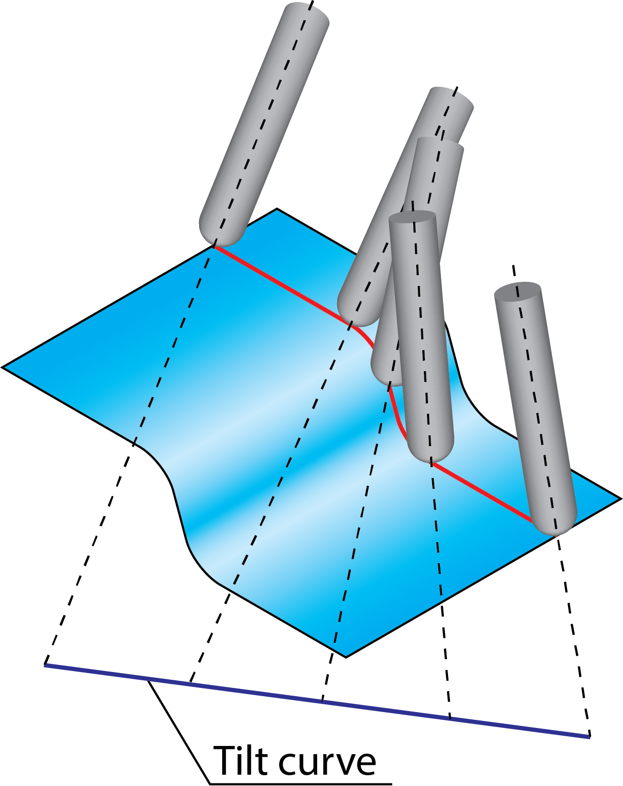
From start to endThe Tilt curve is divided by a number of points equal to the number of cutting passes. The tool axis for each cutting pass is directed from the corresponding point on the Tilt curve. The Tilt curve is divided with a number of points equal to the number of cutting passes. The tool axis for each such cutting pass is directed from the corresponding point on the Tilt curve. |
 |
From start to end for each contourThe Tilt curve is divided by a number of points equal to the number of tool path positions of the specific cutting pass. In certain tool path positions, the tool is tilted according to the vector from the corresponding point on the Tilt curve. The tool tilting changes gradually from the start point of the Tilt curve to its end point. At the start point of a cutting pass, the tool axis is tilted from the start point of the Tilt curve. At the midpoint of the cutting pass, the tool axis is tilted from the midpoint of the Tilt curve. Accordingly, at the end of the cutting pass, the tool axis is tilted from the end point of the Tilt curve. |
 |
Advanced
Using this option, SolidCAM enables you to control the side tilting direction at the intersection of two surfaces with different isometric directions. The Side tilt fanning distance parameter defines the distances from the surface intersection where the transition of side tilting direction is started.
|
This option is not available when the Curve Tilt type is selected as From start to end and From start to end for each contour. |
Angles
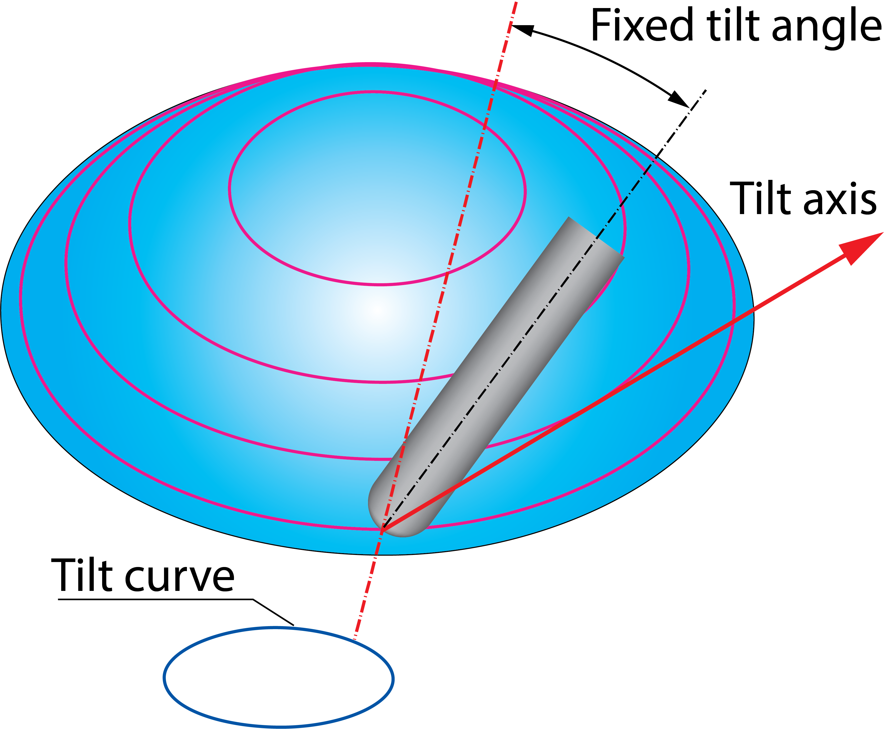
You can define an additional tilting from the calculated vector through the specified tilt curve towards the chosen tilt axis.
Fixed tilt angleThis parameter defines the angle of the additional tool tilting from the vector through the defined curve towards the tilt axis.
|
 |