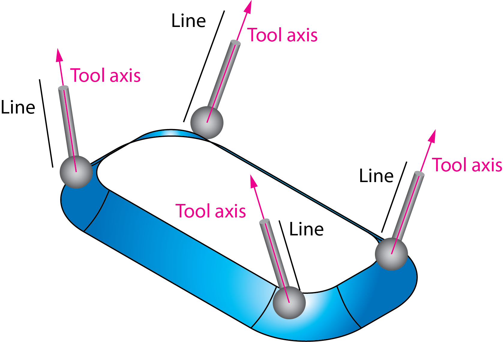
Tilted through lines
This option enables you to define the tool tilting by a number of lines. The tool axis is changed gradually along the tool path trying to pass through the defined lines. The Tilt lines section enables you to choose the lines geometry from the list or define a new one with the Define button, using the Geometry Edit dialog box. The direction of the side tilting gradually changes, passing the defined tilt lines. The Use tilt through option enables you to define how the tool axis is approximated between the defined tilt lines. It has three choices: |
 |
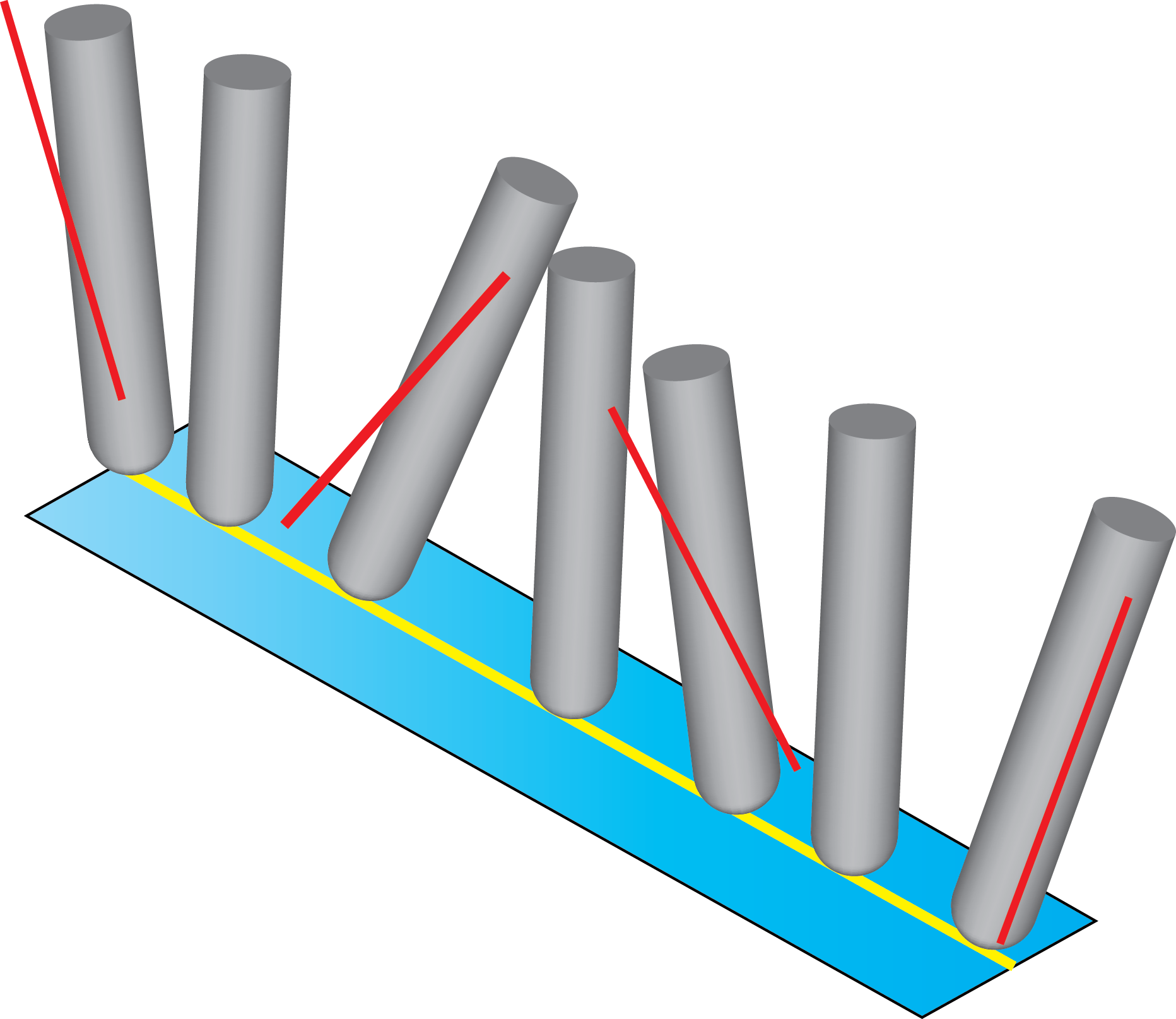
All lines weighted by distanceThe direction of the tool axis is approximated between the tilt lines located close to the tool path, in order to perform smooth transition of the tilting between the tool path positions. In some cases the tilting of the approximated tool path does not coincide with the direction of tilt lines. |
 |
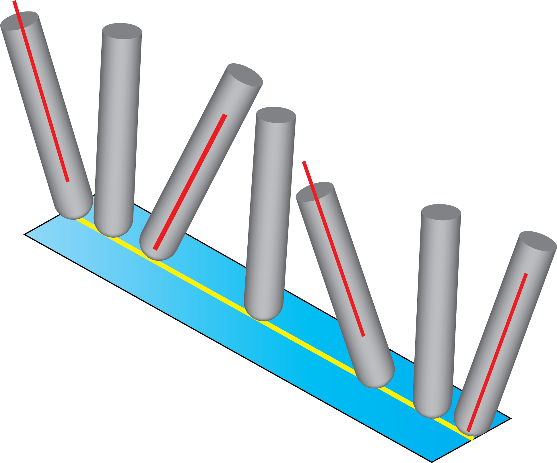
Always use closest two linesThe direction of the tool axis is approximated between two consecutive tilt lines along the tool path. In the resulting tool path, the tool axis coincides with the tilt lines at exact positions and smooth transition is performed between these positions. The maximum snap distance between tilt lines could also be defined in the Tilting lines range section. |
 |
Always closest to surfaceThis option allows you to tilt the tool as defined in the Tilt lines section. This option maintains the tilt by using the tilt lines that are closest distance to the surface. |