Angle range
SolidCAM enables you to limit the tool tilting along the tool path. Click the Limits button to define the angle range parameters.
The Limits dialog box is displayed.
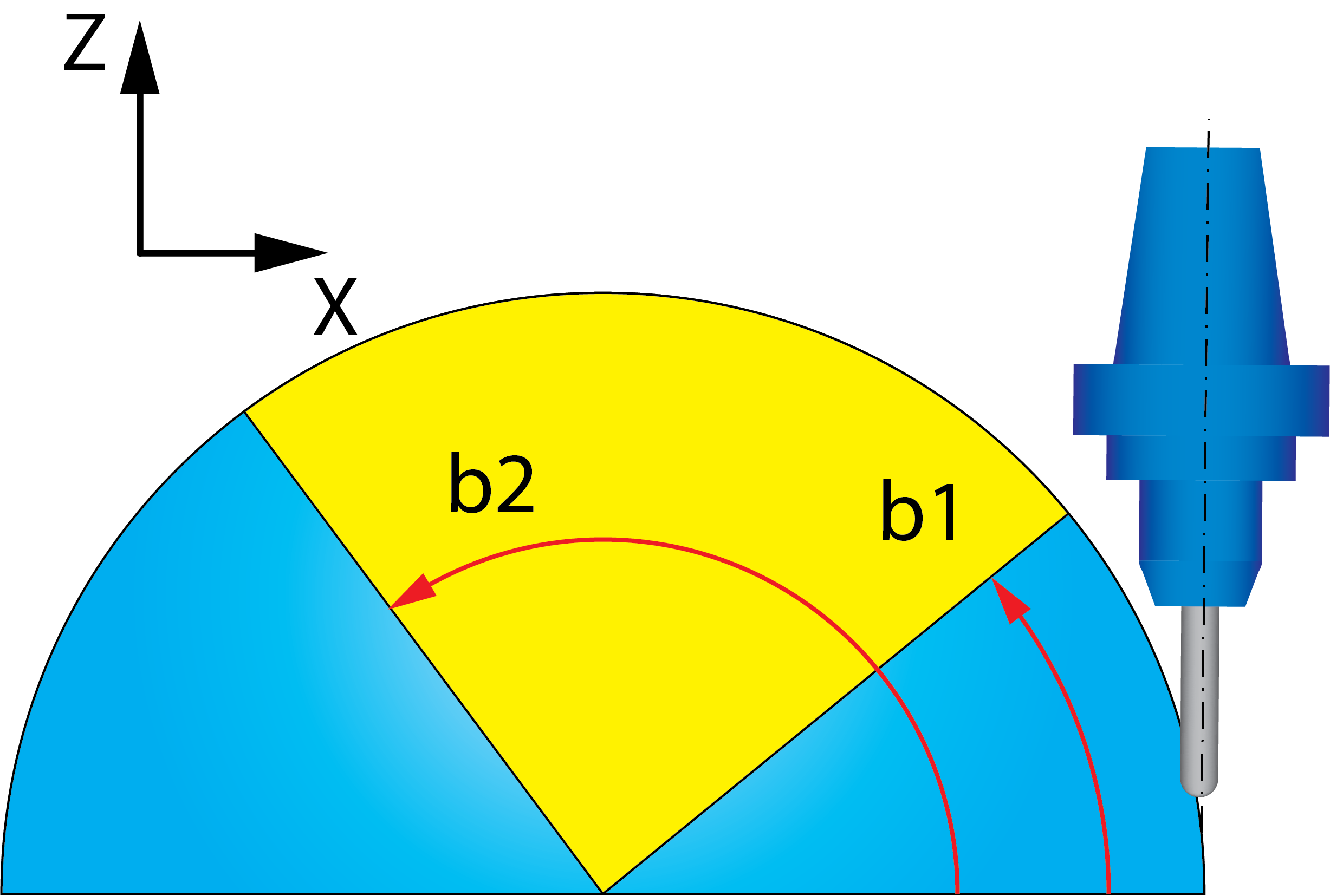
Limit in XZThis option enables you to limit the tool tilting by projecting the tool axis on the XZ-plane of the current Coordinate System. The b1 and b2 parameters define the start and end angle of the limit. |
|
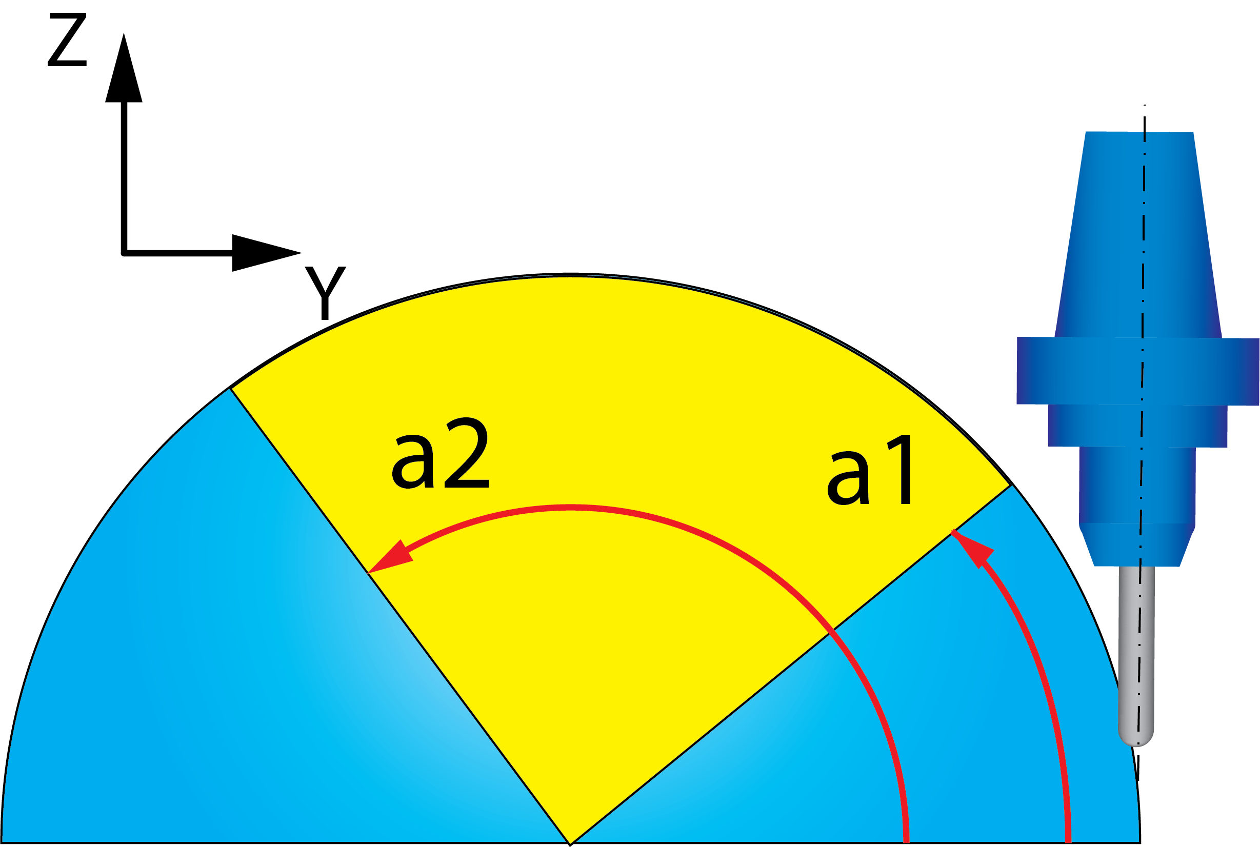
Limit in YZThis option enables you to limit the tool tilting by projecting the tool axis on the YZ-plane of the current Coordinate System. The a1 and a2 parameters define the start and end angle of the limit. |
|
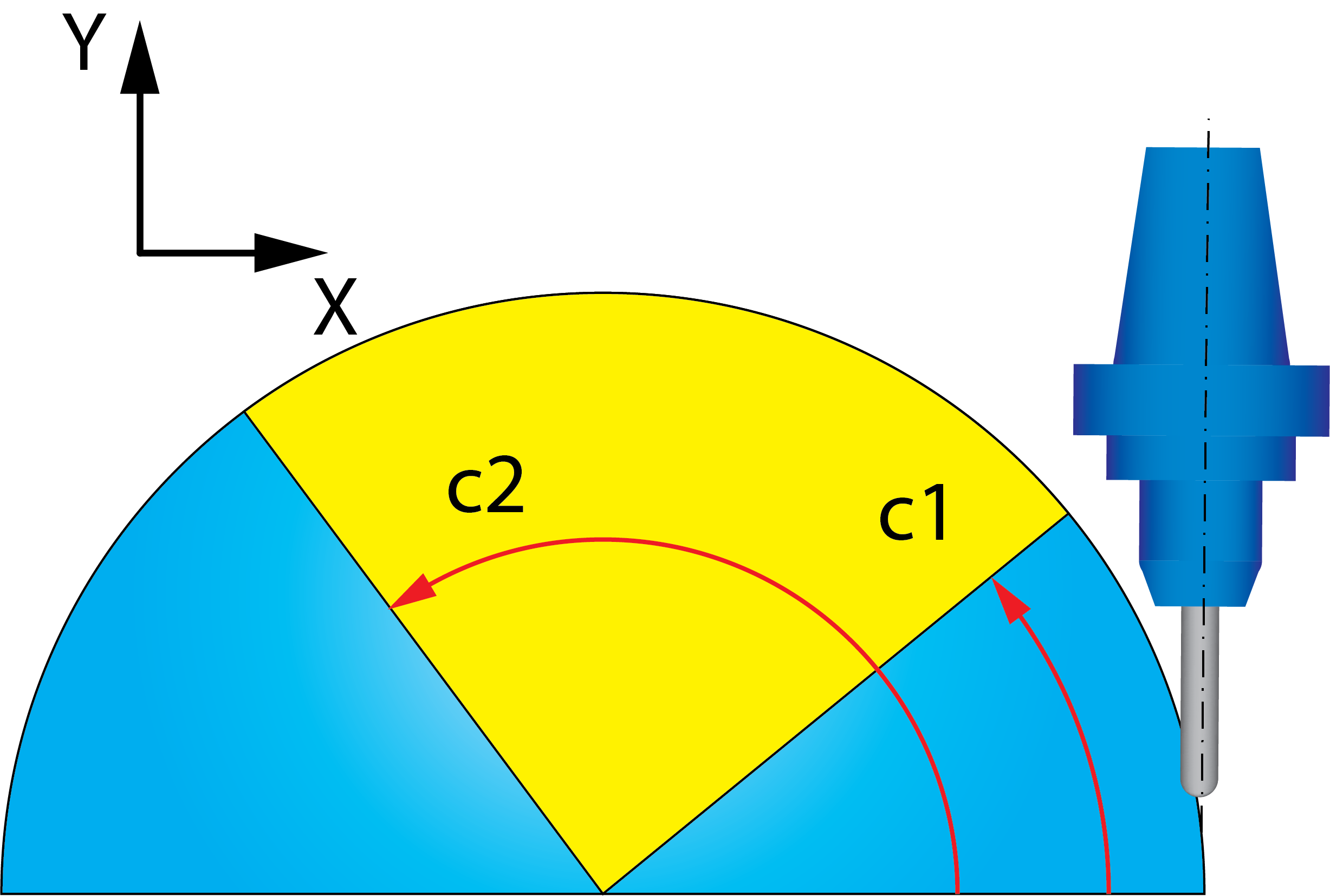
Limit in XYThis option enables you to limit the tool tilting by projecting the tool axis on the XY-plane of the current Coordinate System. The c1 and c2 parameters define the start and end angle of the limit. |
|
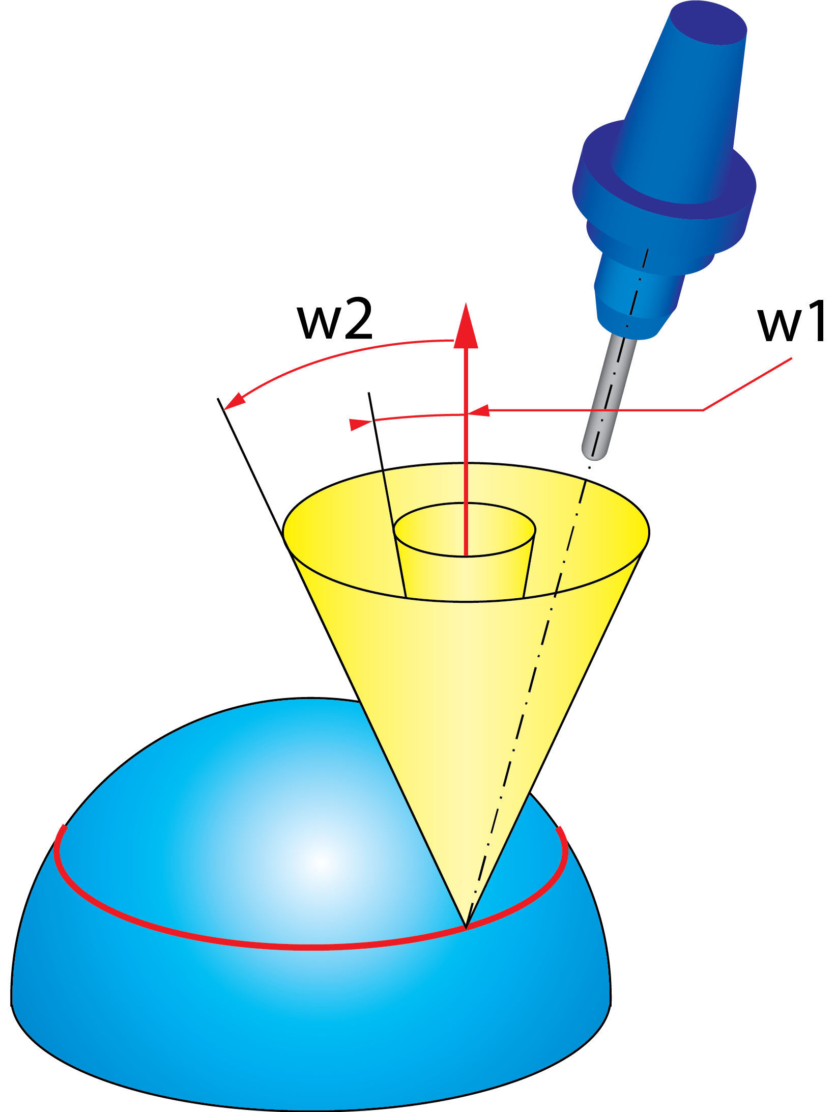
Conical limitSolidCAM enables you to limit the tool tilting between two angles starting from the normal vector to the tool path slice at the contact point. In other words, imagine two cones with different opening angles w1 and w2; the cone vertex is located at the contact point. The tool axis direction is limited between these cones. The orientation of the cones depends on the Cone axis settings. The Cone axis option enables you to define the direction of the limiting cones axis. You can choose either axis of the Coordinate System (X, Y or Z) or define the direction by a user-defined vector. If the tilting along the tool path is defined by a leading curve (e.g. the Cuts along curve option is used), you can choose the Dynamically using leading curve for the Cone axis. In this case, the tool tilting limiting cones are defined relative to a leading curve. |
|