Output format
This parameter enables you to choose the Output format of the current Sim. 5-Axis operation.
4 Axis
This output format is used for 4-axis finish operations such as turbine blade profiles and spiral parts. With this output format, SolidCAM generates a 4-axis GCode with tool tilting around the rotation axis. The tool is normal to the center line. The only tilt strategies available are those that support this type of tilting (4-axis). When this output format is chosen, SolidCAM enables you to define the rotary axis orientation. |
 |
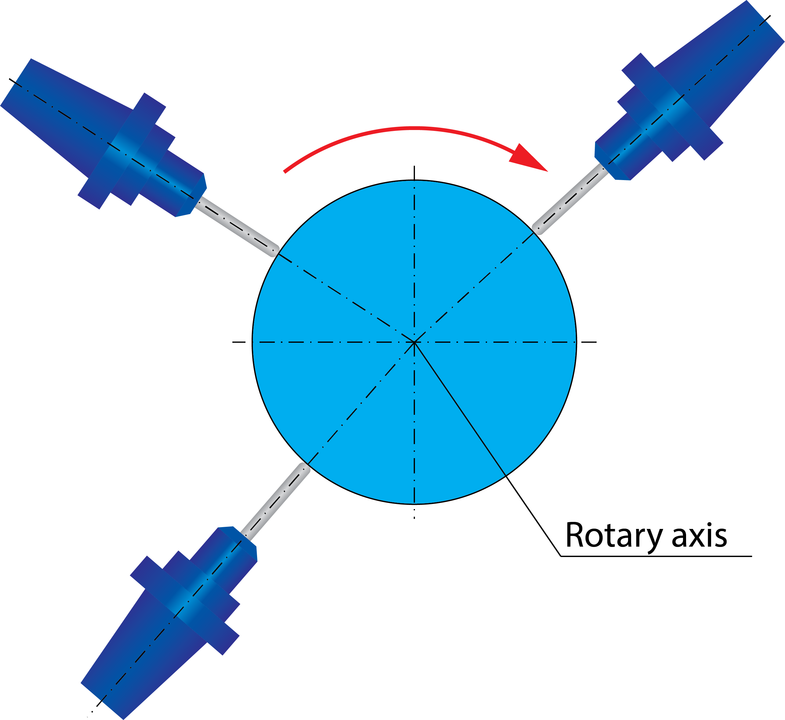
Click Rotary axis to display the 4th Axis dialog box. This dialog box enables you to choose the rotary axis (X-, Y-, Z-axis of the Coordinate System or another User-defined axis).

The Point tool to rotary axis option enables you to define the tool axis orientation when the 4-Axis output is chosen. With this option, the tool is oriented in such way that its axis intersects with the rotary axis. When this option is activated, all other options defining the tool axis orientation (tool tilting) are not available. Axis offset When Point tool to rotary axis check box is selected, the Axis offset parameter allows you to apply a constant offset between the tool and the rotary axis. The offset is applied to the fixed axis and tool machines the workpiece with the appropriate offset, parallel to the fixed axis. The offset value can be set to 0 or any desired value.
|
 |
The GCode generated with the 4 Axis output format is suitable for both 4-axis and 5-axis CNC-machines. When the 5-axis CNC-Machine is used for the 4-axis operation, SolidCAM enables you to set the fifth axis to a specific angle and lock it in this orientation; the 4-axis machining is performed with the fixed fifth axis. In the 5th axis section, the Locked at angle parameter enables you to specify the angle at which the fifth axis is locked. If the Point tool to rotary axis option is selected, you can either lock the 5th axis at the specified angle or make it Relative to cutting direction by selecting the corresponding option.
|
In most of 4-axis CNC-machines the tool axis direction (spindle direction) is always perpendicular to the rotary axis. Therefore, the Locked at angle parameter has to be set to 0 for this type of CNC-machines. Some of the 4-axis CNC-machines have a spindle unit mounted with some fixed tilting angle to the rotary axis. In this case, the Locked at angle parameter must be set to the CNC-Machine fixed tilting angle.
|
5 Axis
With this output format, simultaneous 5-axis output is performed. This output format is used for 5-axis finish and supports all types of 5-axis operations. You have complete control over all of the cutting parameters. The tool can be tilted to any possible direction supported by the machine. All the tilt strategies are available.
|
This output format of operation is available only for post-processors that support 5-axis machining.
|