Working with operation of Channel Synchronization
Labels and drive units
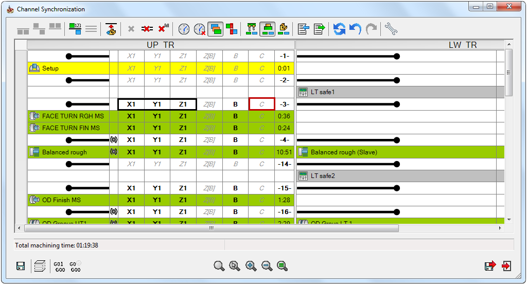
Label is a defined pause you can apply between two operations if a collision is detected. The labels give you information about all the channels that are involved in the operation. The first label in the synchronization window is always numbered 1. The last label is always the largest and takes into account all the channels involved. For example, if you are working on a three channel machine, you can apply some labels to two channels, but the last label will be applied to all three channels.
The labels above and below the Balanced Rough operation are automatically added and cannot be deleted. For example, when you right click on the label that is above or below the Balanced Rough operation, the option of deleting the label is not available to select.
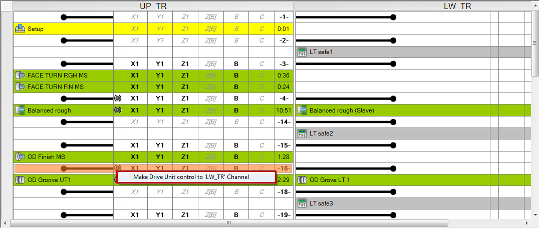
When two operations are synchronized using the same drive unit, you
can define which channel has control over it. If you want to change the
control from upper turret to lower turret, right click Drive
Unit  and select
Make Drive Unit control to ‘LW_TR’ Channel to transfer the control from
upper turret to lower turret.
and select
Make Drive Unit control to ‘LW_TR’ Channel to transfer the control from
upper turret to lower turret.
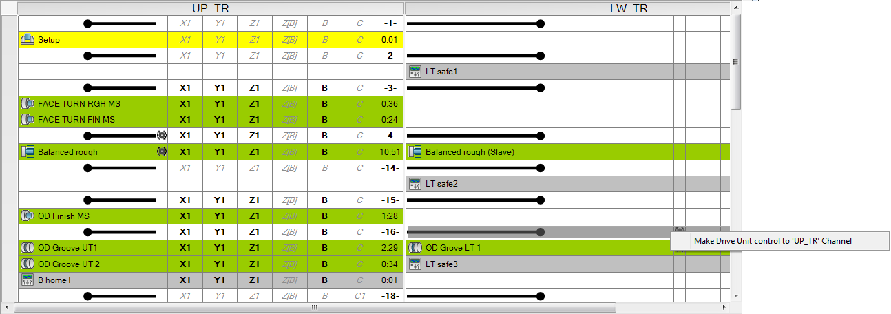
In the image below, the control is transferred to the lower turret and now selecting the drive unit icon gives you the option of transferring the control to the upper turret.
You can use the same Drive Unit by more than one channel at the same time only if it is a Shared Drive Unit. You need to keep in mind the following things while using a shared drive unit:
In Milling operations, the Drive Unit must have same RPM and rotation direction.
In Turning operations, the Turning Station, connected to Drive Unit must have same RPM, rotation direction, and same Spin Type.
Removing the clash in operations
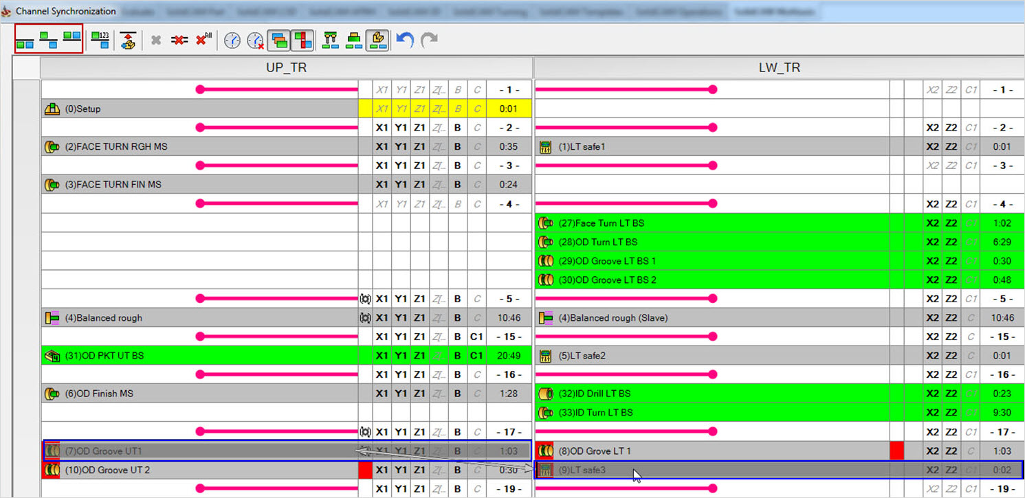
When two operations cannot be synchronized, or are arranged in such a manner that they clash with each other, they are highlighted in red color. Click on the red box to see with which operation the current operation is clashing. Select both the operations and add a label as per your requirement i.e. whether you want to synchronize the operations start to start, start to end or end to end.
In the below image, two operations that are clashing (highlighted using dark blue color) are selected, and on the ribbon available on the Channel Synchronization window, Synchronize selected operations start to start, Synchronize selected operations start to end, and Synchronize selected operations end to end are highlighted.
Axes sharing and control
In the Channel Synchronization window, you can see a number of axes displayed in front of each operation. The axes represented with black color, are used in the current operation. The axes represented by grey color, and italics are not used in the current operation. However, you can see them in front of the operation because all these axes are available on that channel.
You can use the same axis on two channels at the same time, only if they are shared axis. The switching and moving of axis between channels can be done only at the label level.
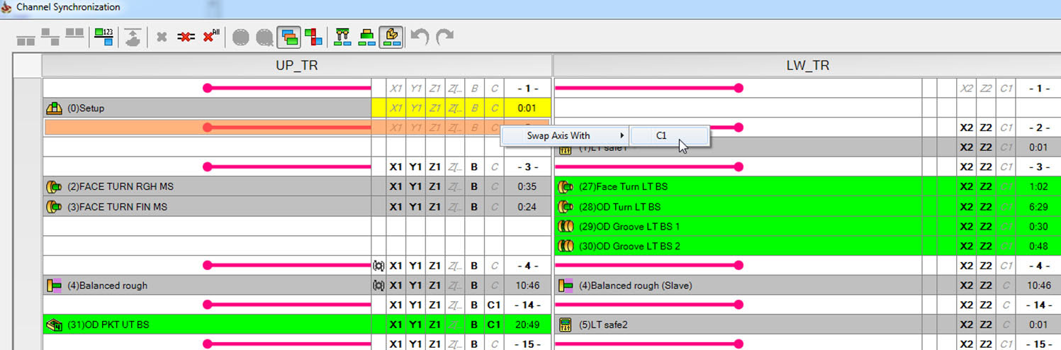
Swap axis option is available on an axis which is not used in the operation and is synchronized end to end with another operation. Click Swap Axis With to swap the current axis with the axis available in the Swap Axis With list.
The guidelines described above explain the general rules and features of the Channel Synchronization operation. You can synchronize the operations in the way you consider is best to utilize the machines for maximum output and minimum machining time.
Channel Synchronization on Single Channel Machines
On Milling machines, where there is only one spindle, SolidCAM’s Channel Synchronization operation can be used in the following ways:
Manage the order of operations in the machine.
Reduce cycle time by optimizing tool change. You can synchronize the tool in such a way that without going back to the home position, the tool can finish machining operation on one part and immediately start the other operation on the second part.