Circular sorting
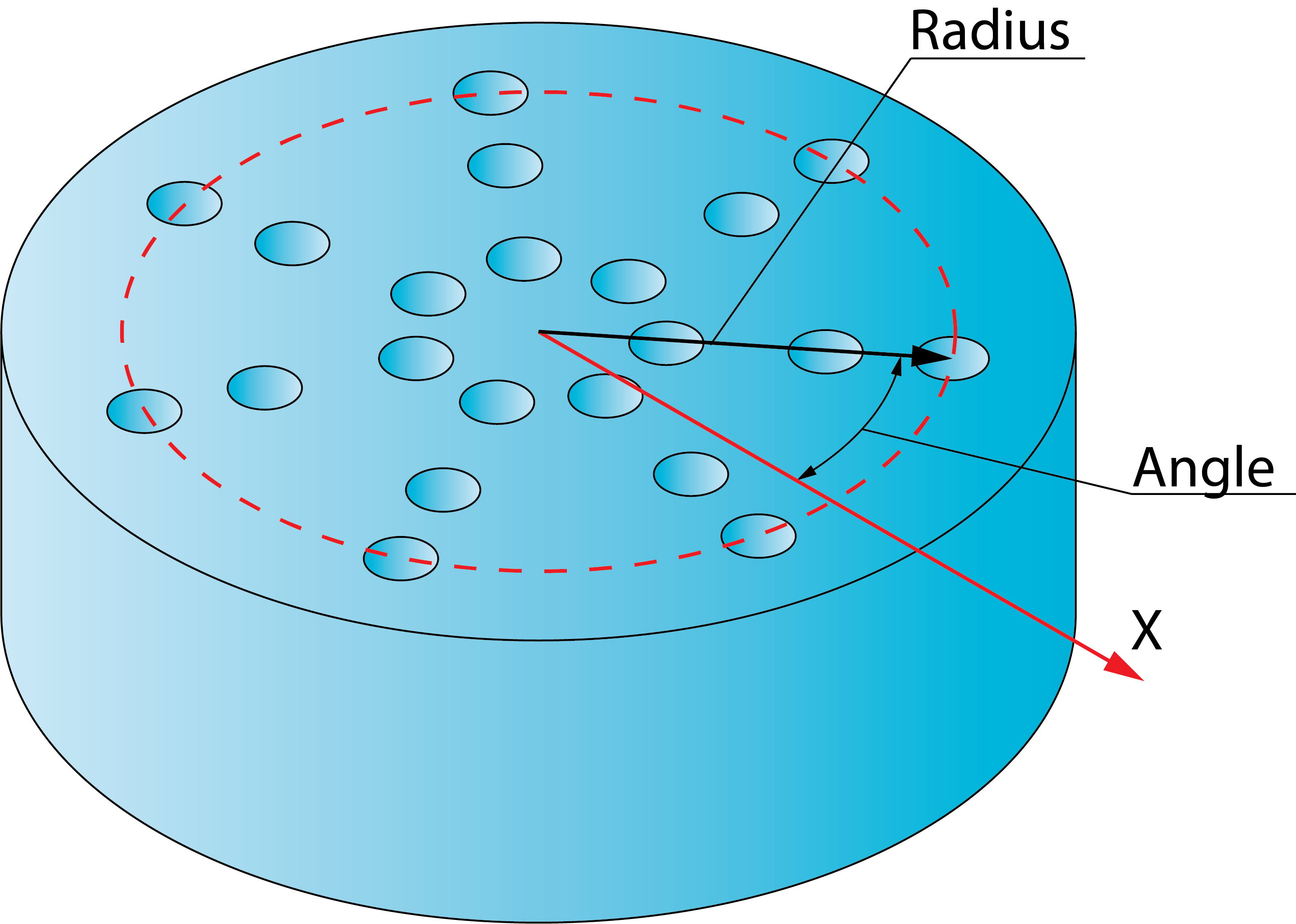
For the ordering of drill positions by all of the circular sorting methods, SolidCAM uses the center point around which the circular pattern is defined. For each drill position of the chosen geometry, SolidCAM determines the radial vector of the drill position from the center point. For each such vector, SolidCAM determines its length (radius) and the angle between the vector and the X-axis at the center point; these parameters are used for further sorting.
Circular pattern
This section contains the following parameters:
This parameter enables you to define the angle at which the start position will be chosen. This angle is defined according to the positive direction of the X-axis at the pattern center. The default value of the parameter is 0°.
The Pick button enables you to define the Start angle by picking a point on the model. The Pick angle point dialog box enables you to pick the position on the model and displays the coordinates of the picked position.
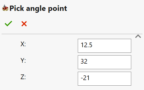
When the position is picked and the dialog box is confirmed, SolidCAM determines the direction vector from the pattern center towards the picked position. SolidCAM automatically calculates the angle between the direction vector and the X-axis at the pattern center and displays the angle value in the Start angle edit box.
During the circular sorting, SolidCAM groups the drill positions into groups of those located at the same radius or into groups of those located at the same angle.
The Tolerance value determines if a drill position belongs to the same radius group or not. For each group of drill positions located at the same radius, SolidCAM determines the start position; each additional drill position to be included into this group must be located at the radius that is within the tolerance from the radius of the start position.
For each group of drill positions located at the same angle, SolidCAM determines the start position; each additional drill position to be included into this group must be located at the angle that is within the angular tolerance (calculated automatically according to the specified tolerance) from the angle of the start position.
Change sorting center
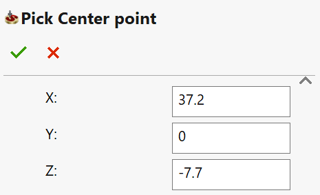
By default, the pattern center is automatically defined at the origin of the Coordinate System used in the current operation. The Change sorting center button enables you to change the pattern center location by picking on the model. The Pick Center point dialog box enables you to pick the center position and displays the coordinates of the picked point.
Circular sorting methods
The following methods are available for advanced circular sorting:
![]()
For each drill position of the chosen geometry, SolidCAM determines the drill position with the maximal radius located at the angle maximally close to the specified Start angle value. This position is accepted as the start position. From this position, SolidCAM performs the machining of all the drill positions located at the same radius; the machining is performed in the clockwise direction.
When all the drill positions located at the current radius are machined, SolidCAM moves to the closest drill position located at the next smaller radius. At this radius, the machining is performed in the same clockwise direction.

![]()
For each drill position of the chosen geometry, SolidCAM determines the drill position with the minimal radius located at the angle maximally close to the specified Start angle value. This position is accepted as the start position. From this position, SolidCAM performs the machining of all the drill positions located at the same radius; the machining is performed in the clockwise direction.
When all the drill positions located at the current radius are machined, SolidCAM moves to the closest drill position located at the next greater radius. At this radius, the machining is performed in the same clockwise direction.

![]()
For each drill position of the chosen geometry, SolidCAM determines the drill position with the maximal radius located at the angle maximally close to the specified Start b value. This position is accepted as the start position. From this position, SolidCAM performs the machining of all the drill positions located at the same radius; the machining is performed in the clockwise direction.
When all the drill positions located at the current radius are machined, SolidCAM moves to the closest drill position located at the next smaller radius. At this radius, the machining is performed in the counterclockwise direction. The next, smaller radius circle (a number of drills located at the same radius) is machined again in the clockwise direction. In such manner, the machining of odd circles is performed in the clockwise direction, the machining of even circles is performed in the counterclockwise direction.

![]()
For each drill position of the chosen geometry, SolidCAM determines the drill position with the minimal radius located at the angle maximally close to the specified Start angle value. This position is accepted as the start position. From this position, SolidCAM performs the machining of all the drill positions located at the same radius; the machining is performed in the clockwise direction.
When all the drill positions located at the current radius are machined, SolidCAM moves to the closest drill position located at the next greater radius. At this radius, the machining is performed in the counterclockwise direction. The next, greater radius circle is machined again in the clockwise direction. In such manner, the machining of odd circles is performed in the clockwise direction, the machining of even circles is performed in the counterclockwise direction.

![]()
For each drill position of the chosen geometry, SolidCAM determines the drill position with the maximal radius located at the angle maximally close to the specified Start angle value. This position is accepted as the start position. From this position, SolidCAM performs the machining of all the drill positions located at the same radius; the machining is performed in the counterclockwise direction.
When all the drill positions located at the current radius are machined, SolidCAM moves to the closest drill position located at the next smaller radius. At this radius, the machining is performed in the same counterclockwise direction.

![]()
For each drill position of the chosen geometry, SolidCAM determines the drill position with the minimal radius located at the angle maximally close to the specified Start angle value. This position is accepted as the start position. From this position, SolidCAM performs the machining of all the drill positions located at the same radius; the machining is performed in the counterclockwise direction.
When all the drill positions located at the current radius are machined, SolidCAM moves to the closest drill position located at the next greater radius. At this radius, the machining is performed in the same counterclockwise direction.

![]()
For each drill position of the chosen geometry, SolidCAM determines the drill position with the maximal radius located at the angle maximally close to the specified Start angle value. This position is accepted as the start position. From this position, SolidCAM performs the machining of all the drill positions located at the same radius; the machining is performed in the counterclockwise direction.
When all the drills located at the current radius are machined, SolidCAM moves to the closest drill position located at the next smaller radius. At this radius, the machining is performed in the clockwise direction. The next smaller radius is machined again in the counterclockwise direction. In such manner, the machining of odd circles is performed in the counterclockwise direction; the machining of even circles is performed in the clockwise direction.

![]()
For each drill position of the chosen geometry, SolidCAM determines the drill position with the minimal radius located at the angle maximally close to the specified Start angle value. This position is accepted as the start position. From this position, SolidCAM performs the machining of all the drill positions located at the same radius; the machining is performed in the counterclockwise direction.
When all the drills located at the current radius are machined, SolidCAM moves to the closest drill position located at the next greater radius. At this radius, the machining is performed in the clockwise direction. The next greater radius is machined again in the counterclockwise direction. In such manner, the machining of odd circles is performed in the counterclockwise direction; the machining of even circles is performed in the clockwise direction.

![]()
For each drill position of the chosen geometry, SolidCAM determines the drill position with the maximal radius located at the angle maximally close to the specified Start angle value. This position is accepted as the start position. From this position, SolidCAM performs the machining of all the drill positions with the same angle (according to the Angle tolerance value) starting from the start position towards the position located at the smallest radius (towards the pattern center).
When the drill position located at the smallest radius is machined, SolidCAM moves in the clockwise direction to the next drill position located at the same smallest radius but at a different angle. From this drill position, SolidCAM performs the machining of the drill positions located at the same angle (according to the Angle tolerance value) towards the drill position located at the greatest radius (from the pattern center outwards). From this position, the tool moves in the clockwise direction to the next drill position located at the same greatest radius, but at a different angle, and so on.
In other words, SolidCAM groups all the drill positions into radial rays, each ray containing a drill position located at the same angle. Each such ray is machined in the opposite direction; the first ray is machined towards the pattern center. The rays are ordered in the clockwise direction.

![]()
For each drill instance of the chosen geometry, SolidCAM determines the drill position with the minimal radius located at the angle maximally close to the specified Start angle value. This position is accepted as the start position. From this position, SolidCAM performs the machining of all the drill positions with the same angle (according to the Angle tolerance value) starting from the start position towards the drill position with greatest radius (from the pattern center outwards).
When the drill position with the greatest radius is machined, SolidCAM moves in the clockwise direction to the next drill position located at the same greatest radius but at a different angle. From this drill position, SolidCAM performs the machining of the drill position located at the same angle (according to the Angle tolerance value) towards the drill position located at the smallest radius (towards the pattern center). From this position, the tool moves in the clockwise direction to the next drill position located at the same smallest radius, but at a different angle, and so on.
In other words, SolidCAM groups all the drill positions into radial rays, each ray containing the drill position located at the same angle. Each such ray is machined in the opposite direction; the first ray is machined from the pattern center outwards. The rays are ordered in the clockwise direction.

![]()
For each drill instance of the chosen geometry, SolidCAM determines the drill position with the maximal radius located at the angle maximally close to the specified Start angle value. This position is accepted as the start position. From this position, SolidCAM performs the machining of all the drill positions located with the same angle (according to the Angle tolerance value) starting from the start position towards the smallest radius (towards the pattern center).
When the drill position with the smallest radius is machined, SolidCAM moves in the counterclockwise direction to the next drill position located at the same smallest radius but at a different angle. From this drill position, SolidCAM performs the machining of drill positions located at the same angle (according to the Angle tolerance value) towards the drill position located at the greatest radius (from the pattern center outwards). From this position, the tool moves in the counterclockwise direction to the next drill position located at the same greatest radius, but at a different angle, and so on.
In other words, SolidCAM groups all the drill positions into radial rays, each ray containing the drill position located at the same angle. Each such ray is machined in the opposite direction; the first ray is machined towards the pattern center. The rays are ordered in the counterclockwise direction.

![]()
For each drill instance of the chosen geometry, SolidCAM determines the drill position with the minimal radius located at the angle maximally close to the specified Start angle value. This position is accepted as the start position. From this position, SolidCAM performs the machining of all the drill positions located with the same angle (according to the Angle tolerance value) starting from the start position towards the drill position with the greatest radius (from the pattern center outwards).
When the drill position with the greatest radius is machined, SolidCAM moves in the counterclockwise direction to the next drill position located at the same greatest radius but at a different angle. From this drill position, SolidCAM performs the machining of drill positions located at the same angle (according to the Angle tolerance value) towards the drill position located at the smallest radius (towards the pattern center). From this position, the tool moves in the counterclockwise direction to the next drill position located at the same smallest radius, but at a different angle, and so on.
In other words, SolidCAM groups all the drill positions into radial rays, each ray containing the drill position located at the same angle. Each such ray is machined in the opposite direction; the first ray is machined from the pattern center outwards. The rays are ordered in the counterclockwise direction.

Related Topics