Constant Z wall machining
Select the check box to machine all areas of the model that are not parallel to the XY-plane, i.e. are not planar. The step down can be controlled by two different options:
Step down options
SolidCAM enables you to choose one of two options for Constant Z wall machining:
Starting from the Upper level, SolidCAM will use the specified step down to calculate each successive Z-level. A value of 20 for the Upper level and a constant step down of 1.5 will produce a tool path on the model contour at Z20, Z18.5, Z17, Z15.5, ... etc. until the Lower level is reached.
SolidCAM will automatically calculate the necessary steps down to produce the specified scallop (cusp height) on the model surface. On steep areas, the step down will naturally be larger than on more level areas.
The Scallop value determines the cusp height of the resulting surface finish. The smaller the value, the smoother the surface finish will be.
On vertical walls of the model, SolidCAM could apply large steps down as this would theoretically result in the scallop value of 0. To avoid large cutting depth and tool load, you can limit the maximum step between two successive Z-levels.
On nearly level areas, the necessary step down to achieve the specified scallop could be very small. You can set a minimum step down value that will override the smaller step down generated by the scallop calculation.
Start machining (Define start by angle)
Value
Enter the angle that defines the start position of the tool path. The value of 0 will generate the tool path start point on the intersection of the contour and the positive X-axis.
Line
When you choose this option, the Define button is activated and you can define a line that determines the orientation of the tool path. The direction vector is defined by picking two points that define the start point and end point of the direction line. The angle of the selected line will be output to the angle field.
Arc approximation
You can create the G2/G3 GCode output from Constant Z operations.
More...
Lead in/Lead out
You can control the way the tool leads in and leads out from the profile. Select an option from the list and enter the distance value for this option.
The following Lead in strategies are available:
More...
Compensation
This option enables SolidCAM to use the tool radius compensation options G4x of the CNC-controller in the GCode output.
Clean contours of flat areas
In prismatic solid parts, if there is a ledge at a depth that falls between down steps or a wall at the edge of a flat bottom of Constant Z machining, SolidCAM can still recognize this ledge or wall and machine it as if in a Profile Operation (between the machining of the previous and next Z-steps).
Connection type
This option enables you to control the way the tool moves between two adjacent tool passes.
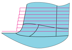
The tool moves in two steps between two adjacent tool passes. If the next pass is lower than the present pass, the tool first moves away from the surface in the XY-direction and then downwards in Z. In case the next pass is higher than the present pass, the tool first moves upwards in Z and then approaches the surface in the XY-direction.
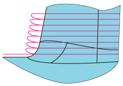
Between two adjacent tool passes, the tool moves away from the contour in a tangent movement. It continues in a 3D arc/spiral movement to the next Z-level and then approaches the contour in another tangent movement.
The Tangential tool path connection smooths lead in/out moves and is especially useful for High Speed Machining. You can avoid "witness marks" on the model that can be caused from a Z approach movement on the model surface.
Approach radius
This parameter defines the radius of the 3D arc that is used to create the tangential move between two successive Z-levels. The value is the maximum radius used as SolidCAM will automatically reduce the radius if the model topology will not leave enough space to approach with the specified radius. This could happen in narrow cavities of the model when a large tool is being used.
Cutting direction (Cut from)
- Top to bottom
The machining starts on the Upper level and continue downward in the -Z direction until the Lower level is reached. The tool finishes one line of the linear pattern, moves directly to the next line and so on. It mills forward and backward without leaving the material, thus constantly changing between climb milling and conventional milling.
- Bottom to top
The machining starts from the Lower level and continue towards the Upper level.
Milling type
Climb
The tool cuts on the left side of the model contour. Unless the selected Open contour strategy is set to Zigzag, contours are always machined in the climb milling direction.
Conventional
The tool will cut on the right side of the model contour. On outside contours, this will generate a tool path in clockwise direction.
Open contour strategy
This field controls the milling direction on contours that cannot be closed because the model or a specified working area does not enable SolidCAM to continue the tool path in a closed loop.
One way
The tool will retreat to the Clearance level and move to the start point of the next tool path, always keeping the cutting direction specified in the Milling type.
Zigzag
This option enables the tool to change the cutting direction when it encounters open contours on the model. The milling direction on open contours will switch between climb and conventional milling until the open contour has been finished. With the Zigzag option, rapid moves from Z-level to Z-level will be greatly reduced.
Fillet size for last cut
This option enables you to add a radius to sharp corners of the tool path without having to change the geometry.
More...
Related Topics