Defining the coordinate transformation
In some cases, the CNC-Machine spindle is not aligned in the positive Z-axis direction. For example, an angular attachment enables you to transform the vertical spindle rotation (around the Z-axis) into the horizontal rotation (around the Y-axis). In this case, the Z-axis of the spindle unit is not parallel to the default main spindle direction.
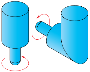
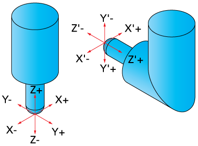
In the illustration below, the default XYZ coordinates describe the main spindle direction (coordinate system of the CNC-Machine). The X’Y’Z’ coordinate system describes the angular attachment. These coordinate systems have different axes orientations.
The coordinate transformation between the default coordinate system and the spindle coordinate system has to be performed in order to enable correct execution of the tool path by the tool mounted in the spindle unit.
To perform the necessary coordinate transformation, you have to add a new coordinate transformation item into the CNC-Machine definition tree. Hierarchically, this item has to be "parent" to the holder_transform item.
The element properties table contains a transformation matrix. f
Using this matrix, you can define the transformation of the coordinate system. In other words, you can define the orientation and location of a transformed coordinate system relative (X’Y’Z’) to the coordinate system of the CNC-Machine (XYZ).
The columns of this matrix describe the axis orientation of the CNC-Machine coordinate system relative to the transformed coordinate system. The X column defines the direction of the X-axis, the Y column defines that of the Y-axis, and the Z column defines that of the Z-axis. The Shift column defines the offset of the transformed coordinate system origin relative to the CNC-Machine coordinate system origin.
The rows of the matrix define the orientation of the transformed coordinate system relative to the CNC-Machine coordinate system. The X row defines the direction of the X-axis, the Y row defines that of the Y-axis, and the Z row defines that of the Z-axis.
|
By default, the diagonal of the transformation matrix is filled with 1 values. This means that the initial coordinate system of the CNC-Machine and the transformed coordinate system are the same and coordinate transformation is not performed. Such transformation matrixes were used for the station_transform and adaptor_transform definition. |
In case a transformation is required, you have to fill the transformation matrix.
The transformed coordinate system for the angular attachment discussed before is obtained by the 90° rotation of the CNC-Machine coordinate system around the X-axis.
![]()
The resulting transformation is as follows:
![]()
Related Topics