Defining the tool
At this stage, you can review the default tool and its kinematic relationship with the CNC-Machine components.
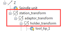
The tool with holder is mounted on the CNC-Machine spindle unit (Z-axis). The tool item is preceded by a series of coordinate system transformations that define the kinematic relationship between the tool and the CNC-Machine components. In the default state, the station_transform, adaptor_transform, and holder_transform items have the same values, but they can change when Machine Simulation of a certain part is loaded.

The tool_tip_1 item defines the default model of the tool.

|
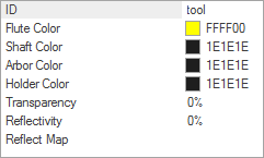
The tool geometry with the hard-coded name Tool is related to the tool.stl file. In the process of the CNC-Machine definition this file does not exist. It will be automatically created during the simulation. Every time during the simulation this file will be overwritten with the actual tool data. |
Related Topics