Edit Tool Path
The operation of Edit HSR/HSM Tool Path enables you to easily edit/trim or modify the generated tool path, using Boundaries, and Z levels.
This option is available in the CAM Tree after the HSR/HSM operation is calculated. Right click the operation you want to edit and select Edit HSR/HSM Tool Path.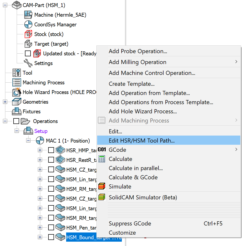 This opens the Edit HSR/HSM window. Once you click the
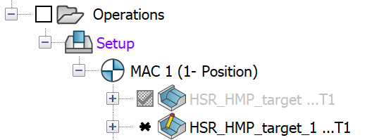
Save icon in the Operations window, the original operation is suppressed
in the CAM Manager Tree
and the edited operation is created below
it with the Edit icon on it.
This opens the Edit HSR/HSM window. Once you click the
Save icon in the Operations window, the original operation is suppressed
in the CAM Manager Tree
and the edited operation is created below
it with the Edit icon on it.
Source Operation
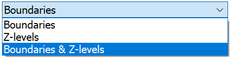
The Source operation page of Edit HSR.HSM operations window displays the name of the operation which is currently open for editing. The Edit Toolpath Strategy section enables you to define the tool path editing strategy using Boundaries, Z-level, and Boundaries & Z-level.
Boundaries
When you select the Boundaries option, you can trim a set of finish passes using a 2D or 3D boundary on the Boundaries and Z-levels page. The 3D boundaries are theoretical rest areas,rest areas, shallow areas, tool contact areas. Working with 3D Boundaries function, gives a better result on steep faces.
|
The section of Z-levels is unavailable on the Boundaries and Z-levels page when the Boundaries option is chosen on the Source operation page. |
Z-levels
The z-limits are the highest and lowest positions for the cutter - the range in which it can move during the pass – and can be altered to modify the passes after they have been created. When you choose this option, the tool path is edited only between the sepcified Z-levels values that you set on the Boundaries and Z-levels page.
|
The section of Boundaries is unavailable on the Boundaries and Z-levels page when the Z-levels option is chosen on the Source operation page. |
Boundaries & Z-levels
When you select this option, the tool path is edited using the chosen boundary and the specified Z-levels.
Tool
The Tool tab displays the tool used in the operation. The tool parameters cannot be edited in the Edit HSR/HSM Operations window. On the Data tab, only the options of Link down, Link up and Rapid are available for editing.
Boundaries and Z-levels
This page enables you to define the boundaries and Z-levels to edit the tool path.
Boundary Type
The Boundary type section enables you to create the boundary automatically or manually.
Boundary name
The Boundary name section enables you to define a new boundary or choose an existing one.
The Boundary offset section enables you to apply an additional positive or negative offset value to the defined boundary.
The Z-levels section enables you to specify the maximum and minimum z-limits for editing the tool path.
Keep tool path outside the Boundary
When this check box is selected, everything inside the trimming boundary is trimmed while the tool path is kept outside the selected boundaries.
When this check box is not selected, all exterior pass information is removed while the tool path is created only inside the selected boundaries.