Rest Material
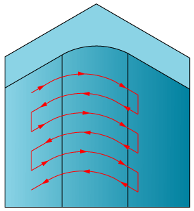
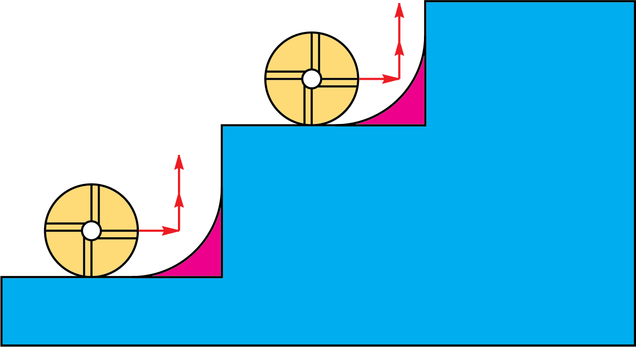
With the 3D Roughing strategy, SolidCAM generates a number of sections parallel to the XY-plane of the CAM-Part Coordinate System. These sections are generated with a Z-step defined either by constant step down or by scallop. In each of these sections, the section profile geometry is used to produce a pocket tool path. The Rest material feature enables SolidCAM to machine in each of these sections only in areas the previous tool has not been able to machine.
When a large tool is used around the profile, it leaves material in corners that it cannot enter.
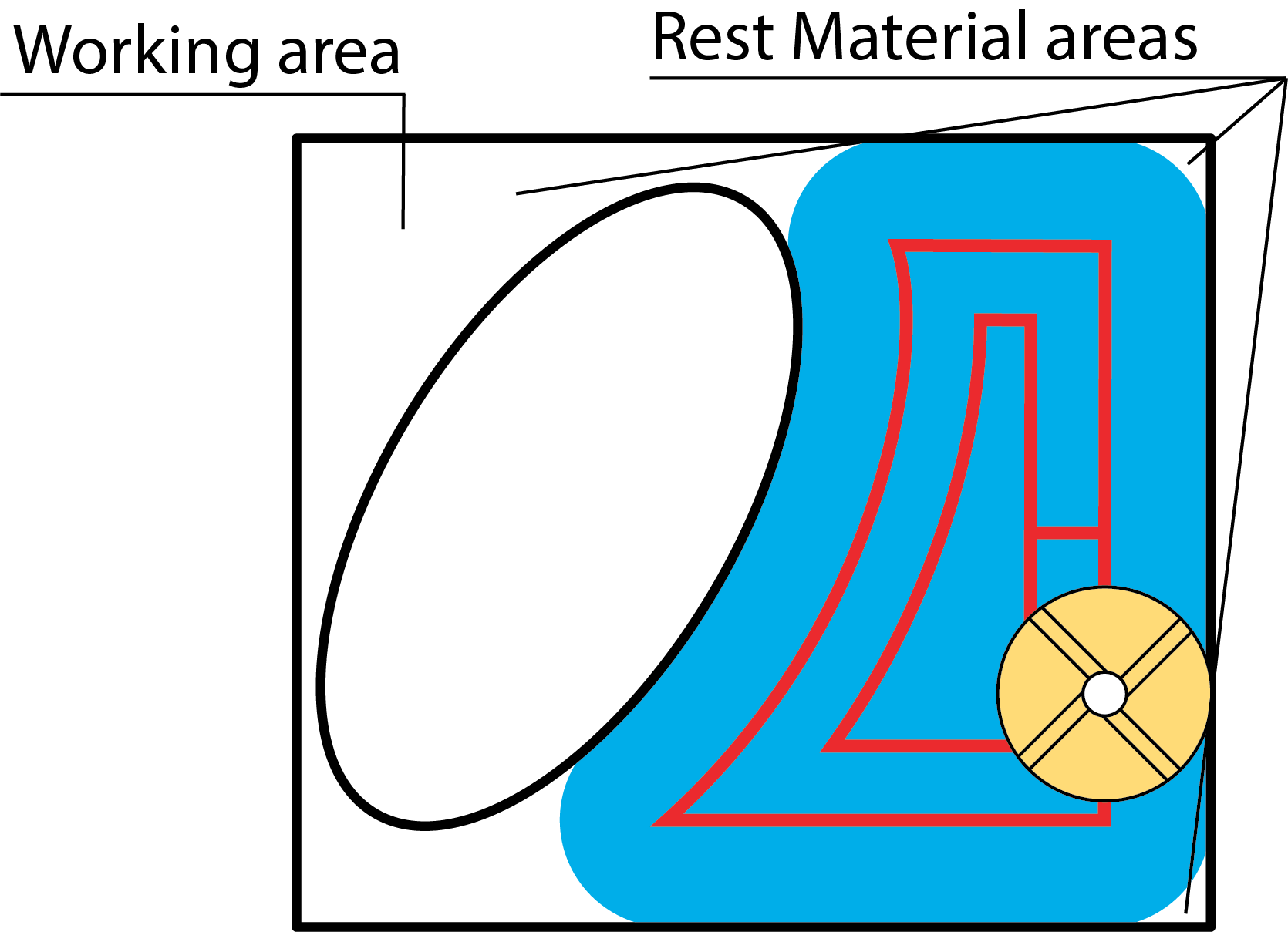
The Rest material option enables you to remove the material from this area without defining a new geometry.
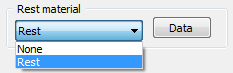
The Rest Material dialog box is displayed:
In this dialog box you have to define the following parameters:
Previous tool diameter - the diameter of the rough end mill used in the previous operation. The button enables you to display the Part Tool Library and select the previously used tool so that its diameter appears in the edit box.
Previous wall offset - the wall offset of the previous operation.
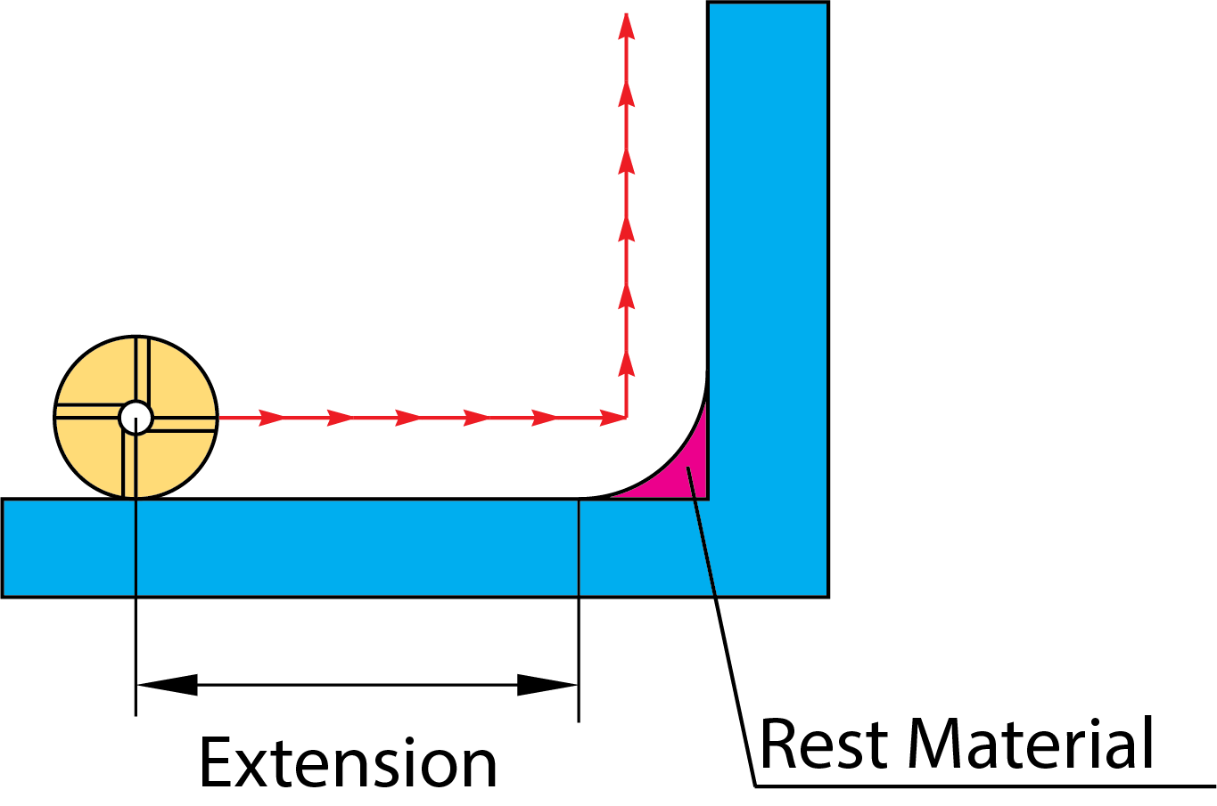
Extension - the overlap distance that you would like to start and end from the previous larger end mill.
Milling type
If you choose Separate areas, SolidCAM generates a profile or pocket tool path to clean areas that the previous tool could not mill. The Around profile strategy generates a closed profile to mill the rest material.
Separate areas: SolidCAM machines only areas not machined with the previous tool.
Around Profile: SolidCAM machines the whole profile.

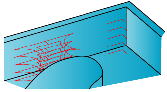
In Pocket operations with the Separate areas machining strategy, SolidCAM generates two types of tool paths, depending on the volume of the rest material and on the previous and present tool diameters:
|
|
Pocket-style tool paths |
Profile-style tool paths |
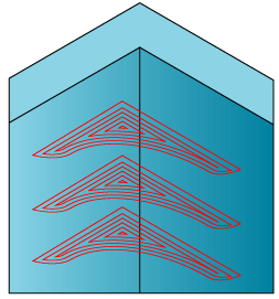
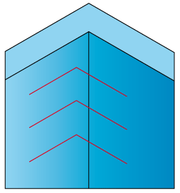
SolidCAM generates a pocket or a profile tool path in each area of the rest material.
Pocket-style tool path areas can be either open or closed depending on the approach possibilities.
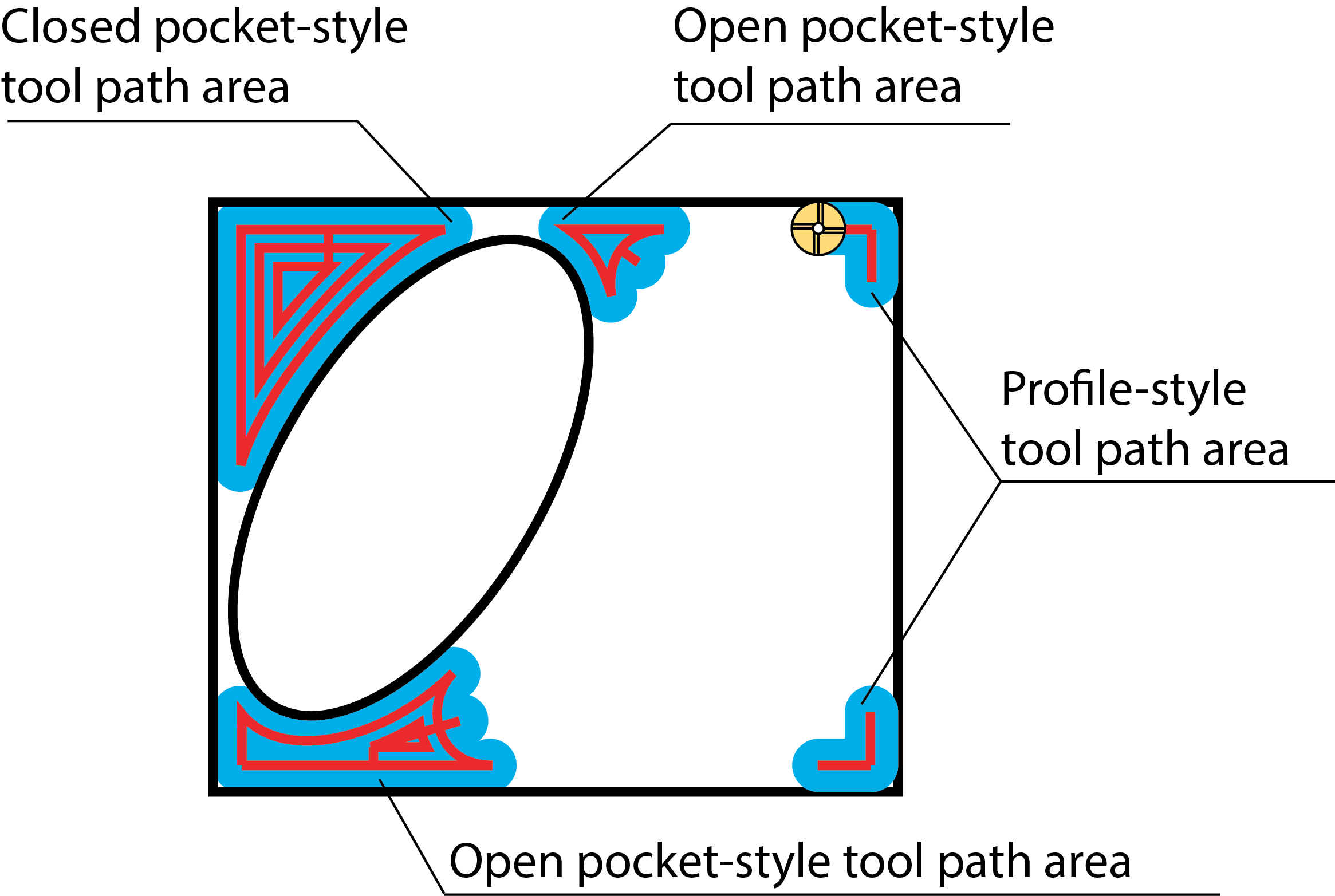
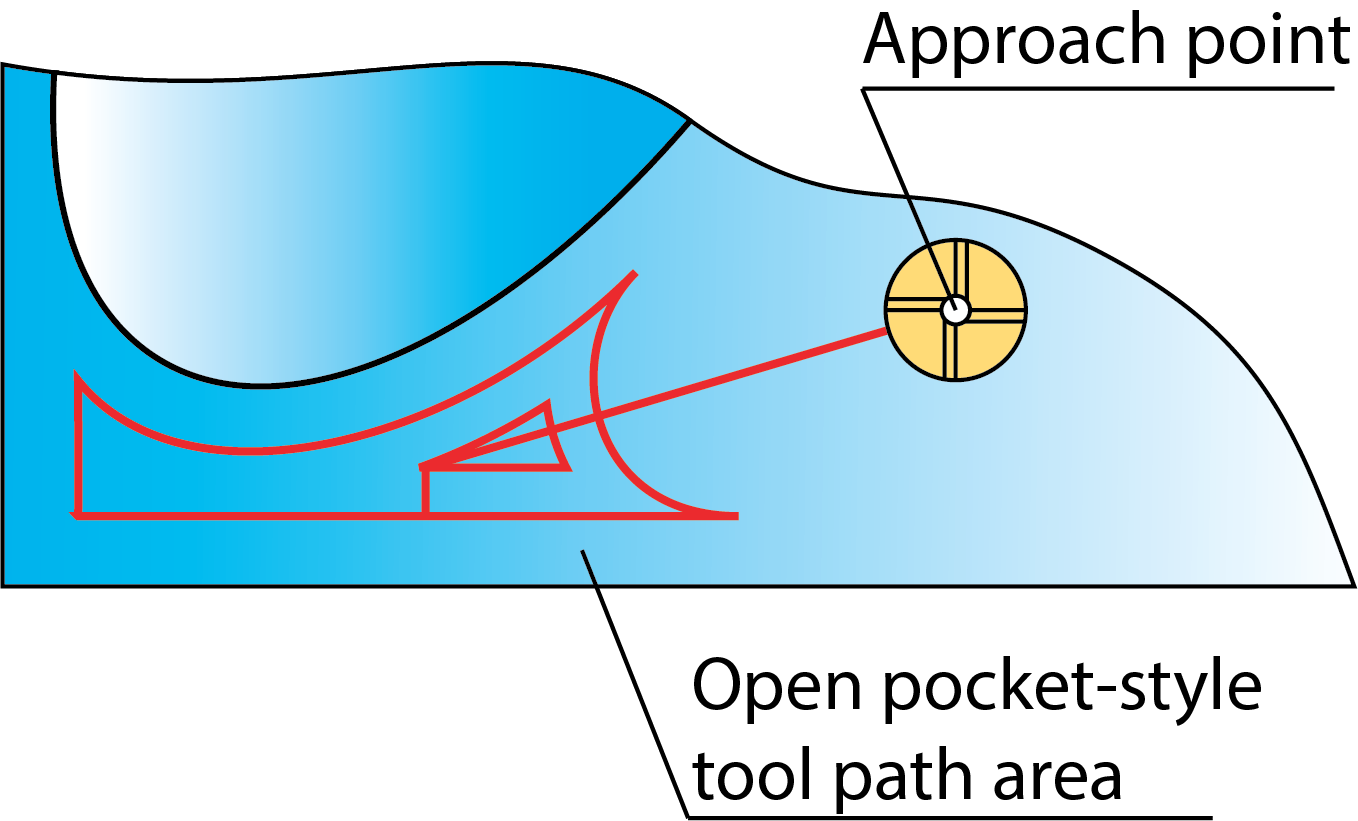
The approach to the open pockets can be performed from the machined space in contrast to the closed pockets where the approach from the outside is unavailable.
SolidCAM automatically determines the optimal point for the approach to the open pocket areas.
Lead in/out
The Lead in and Lead out options define the approach/retreat strategy for the Profile-style tool path areas. The following strategies are available:
None
Normal
Arc
Pocket/Profile
The check boxes selected in the Pocket and Profile sections determine which of these tool paths are cut:
- Island – only tool paths that touch the pocket islands are cut.
- Island + Wall – tool paths that touch both the pocket wall and islands are cut.
- Wall - only tool paths that touch the wall are cut.
Compensation
When the Compensation dialog box is selected, tool radius compensation commands are used (G41, G42 for Fanuc) in GCode output.
Open contour strategy
This option enables you to define the direction of the open contours machining.
One way
The tool moves along an open contour at a specific Z-level. At the end of the contour, the tool moves with rapid feed (G0) to the Safety distance and then starts machining the open contour at the next Z-level. The tool will always use climb or conventional milling.
Zigzag
The tool finishes an open contour at the specific Z-level and then moves directly to the next Z-level and so on. It mills forward and backward without leaving the material, thus constantly switching between climb and conventional milling.