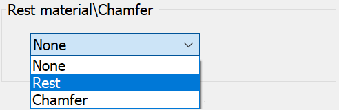
Rest Material\Chamfer
Rest material
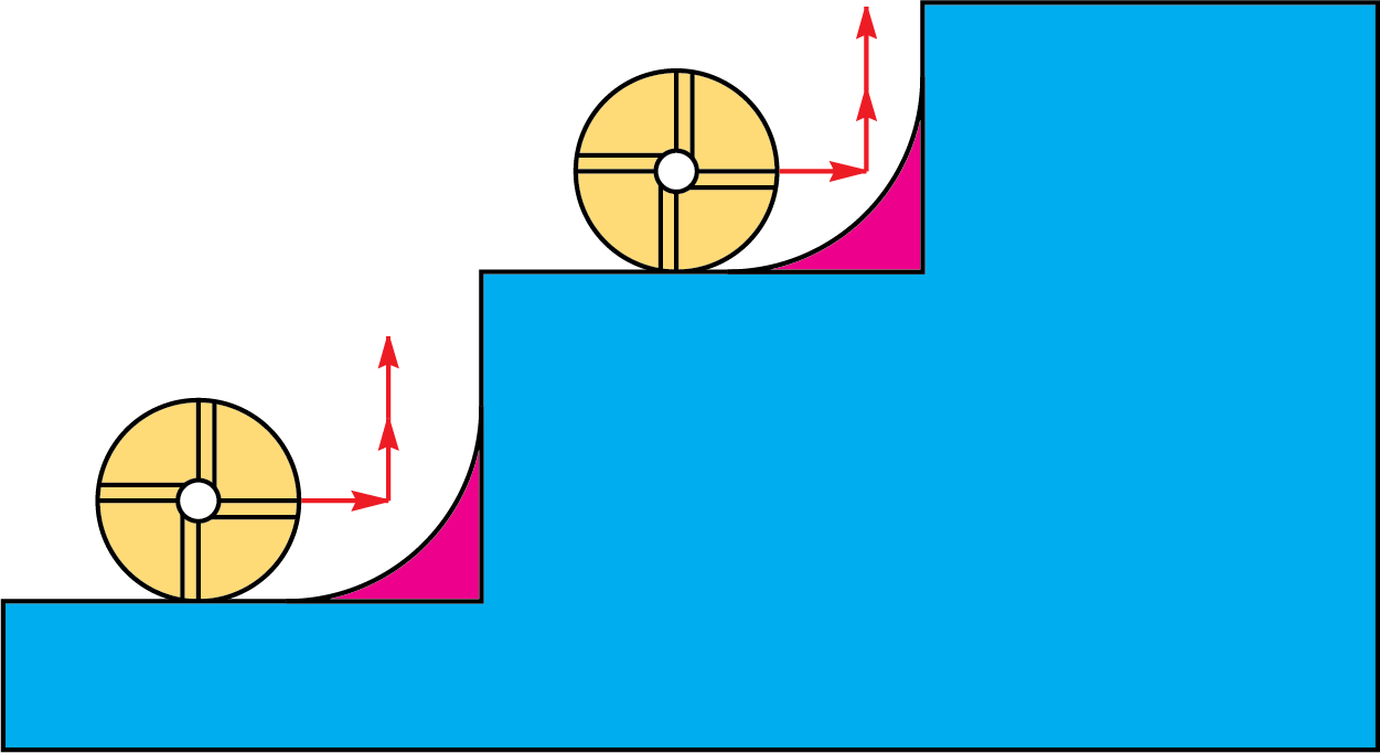
When a large tool is used around the profile in Pocket machining, the tool leaves material in the areas that it cannot enter.
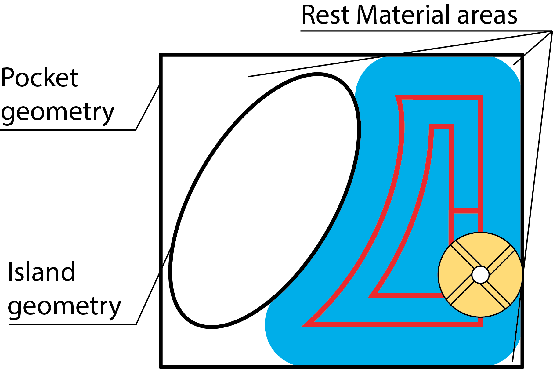
The rest material option enables you to remove the material from this area without defining a new geometry.
The Rest Material dialog box is displayed:
In this dialog box, you have to define the following parameters:
Previous tool diameter - the diameter of the tool used in the previous operation.
Previous wall offset - the wall offset used in the previous operation.
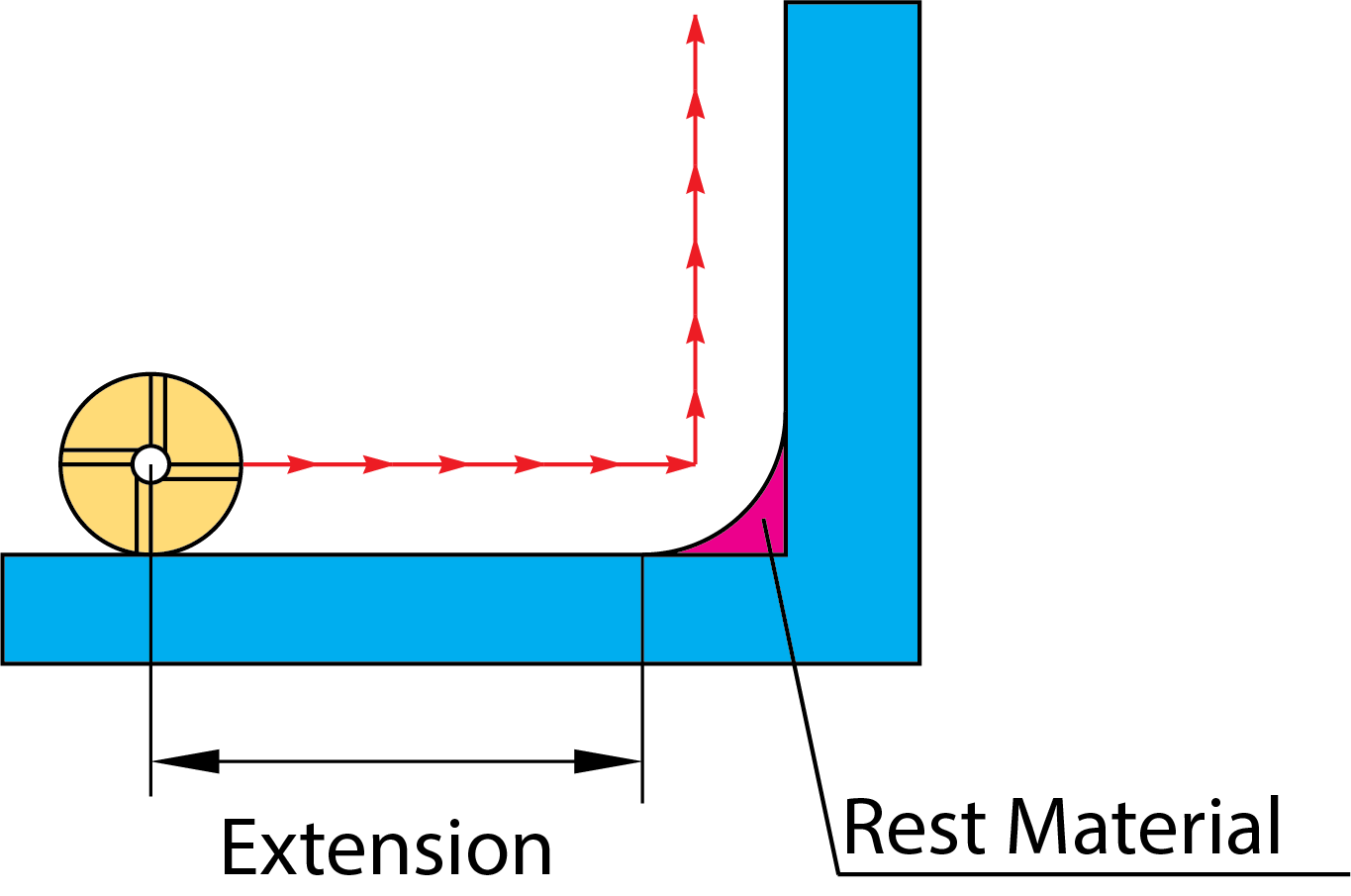
Extension - the overlap distance that you would like to start and end from the previous larger end mill.
Milling type
When the Separate areas strategy is chosen, SolidCAM generates a profile or pocket tool path to clean areas that the previous tool could not mill. The Around profile strategy generates a closed profile to mill the rest material.

In Pocket operations with the Separate areas machining strategy, SolidCAM can generate two types of tool paths, depending on the volume of the rest material and on the previous and present tool diameters:
|
|
Pocket-style tool paths |
Profile-style tool paths |
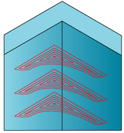
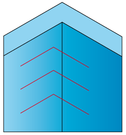
SolidCAM generates a pocket or a profile tool path in each area of the rest material.
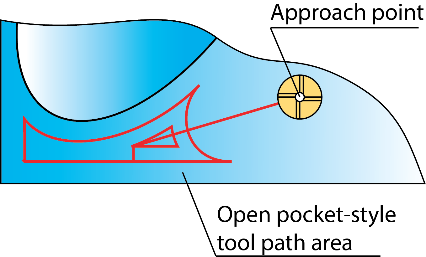
Pocket-style tool path areas can be open or closed depending on the approach possibilities.
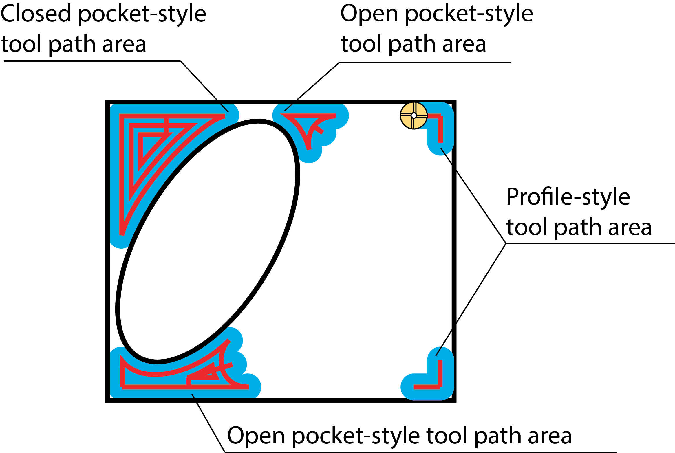
The approach to the open pockets can be performed from the machined space in contrast to the closed pockets where the approach from the outside is unavailable.
SolidCAM automatically determines the optimal point for the approach to the pocket areas.
When the Rest Material option is chosen in the Pocket Operation dialog box, the Lead in option provides you with the following strategies used for the approach to Profile-style tool path areas:
- None
- Normal
- Arc
- Tangent
More...
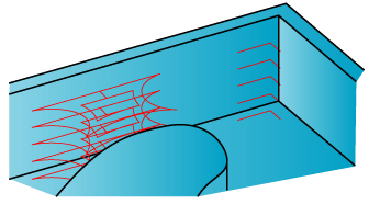
Chamfer
This option enables you to add a chamfer to the edge of your part.
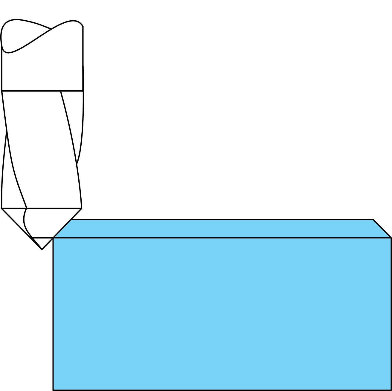
The following tool types can be used for chamfering:
On the Levels page, the Depth parameter defines the size of the chamfer edge.
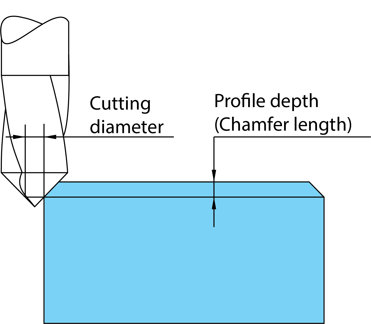
When using the Chamfer option for pockets, the following parameters must be defined on the Chamfer tab:
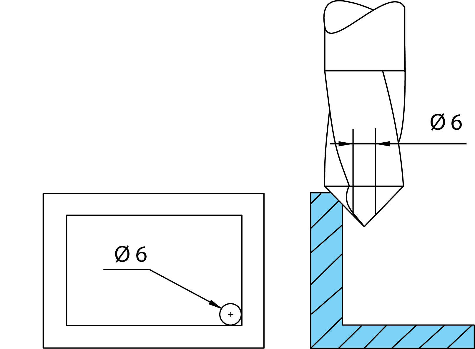
Cutting diameter – defines the starting cutting diameter of the tool.
Previous tool diameter button– enables you to choose the previous tool from the Tool Table or enter the value in the text field.
Previous wall offset – defines the wall offset remaining after a previous operation.
Extension/Overlap – defines the overlap distance that you would like to start and end from the previous larger end mill.
Feed in internal corners – defines the feed rate you would like the tool to travel when cutting in corners (G2).
|
If you choose to chamfer a part with sharp corners, the Cutting diameter should be the same as the last tool used in machining the geometry so that the chamfer is equal all around.
|