Tool sheet documentation
This option enables you to summarize the CAM-Part information by generating a tool sheet documentation in the DOCX, HTML, RTF or XLS format.
Generating the tool sheet
For each tool sheet project, SolidCAM creates the Doc folder in the CAM-Part directory for saving the tool sheet file. In this folder, the following subfolders are automatically created:
Tools Images subfolder for image files of the tools used in the part operations
Images subfolder for image files of the machined part and
Operations Images subfolder for image files of a selected operation
The following tool sheet generation commands are available:
Capturing the CAM-Part image
Right-click the CAM Part header and choose Documentation (Toolsheet) > Capture Image.
Selecting Capture Image displays the Image name text box which enables you to customize the name of the saved image.
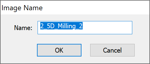
This command enables you to capture an image of the CAM-Part as it is displayed in the SOLIDWORKS Graphics Area, save it in the PNG format and store it in the Images folder. Later this image file can be attached to your tool sheet.
Capturing the operation image
Right-click an Operation in CAM tree and choose Documentation (Toolsheet) > Capture Operation Image.
Selecting the Capture Operation Image enables you to capture an operation image of the CAM-Part as it is displayed in the SOLIDWORKS Graphics Area. The image of the selected operation is saved in PNG format in the OperationsImages folder. After successfully capturing the image the following message is displayed:

Later this image file can be attached to your tool sheet.
|
This option is disabled if you select more than one operation in the CAM tree. |
Definition of tool sheet parameters
The Tool Sheet command displays the Tool Sheet Extra Parameters dialog box, which enables you to define and manage the content of the documentation file.
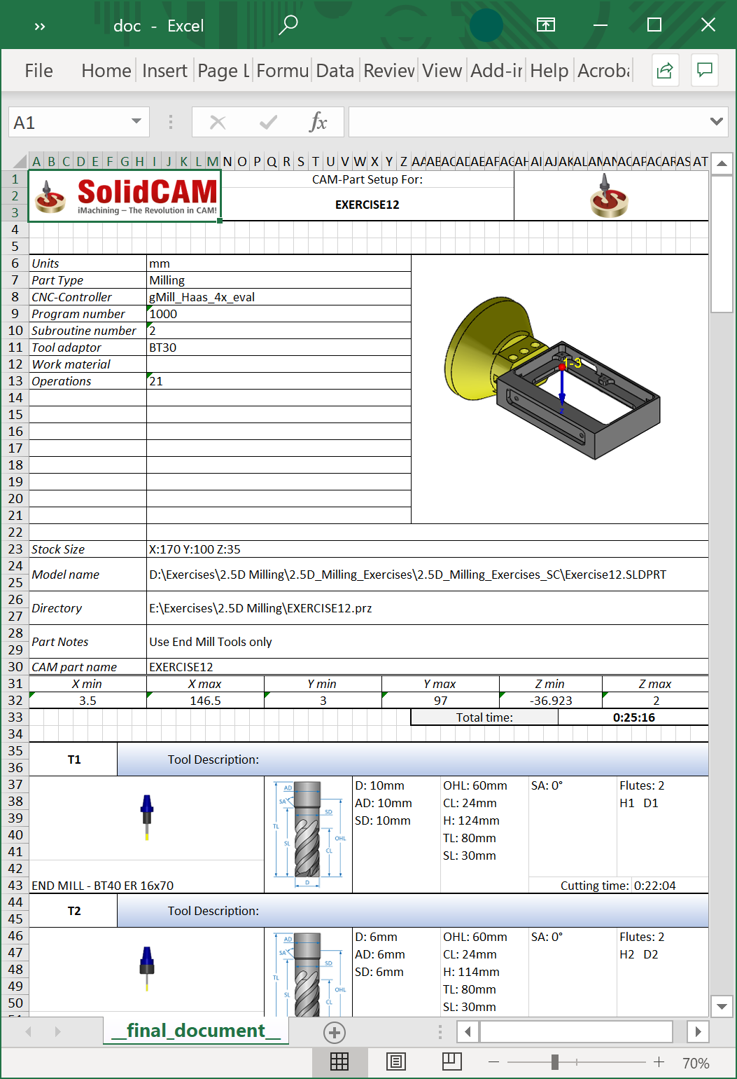
The output file
The output tool sheet file consists of the following sections:
Show Last Tool Sheet
This command enables you to display the last generated tool sheet for the current CAM-Part, instead of generating it again. The Tool Sheet Extra Parameters dialog box is displayed so that you can view the defined parameters of the last tool sheet generation.
In this dialog box, you can edit only the Style and the Sections parameters to alter the document appearance and define which sections of the last tool sheet you want to display.
The Show button displays the generated tool sheet.
Tool sheet template definition in the XLS format
Before you generate your tool sheet, you need to define the tool sheet template in the Microsoft Excel application.
|
To view the tool sheet folder save the CAM part in .prt format. |
Related Topics