Passes
The Passes page enables you to define the technological parameters needed to generate the tool path for the SolidCAM Undercut Milling operation.
The Passes tab displays the major parameters that affect the generation of tool path passes.
Step down
This option allows you to define intermediate slices based on depth distance between them. The Step Down parameter defines the spacing of the passes along the tool axis. The passes are spaced at the distance that is set.
Sorting
The Sorting section displays the options that enable you to define the sorting of the tool path passes.
Cutting method
This option enables you to define how the cuts are connected.
One way
When this option is chosen, all cuts are machined in the same direction. The tool performs the machining of a cut in the specified direction, then moves to the start of the next cut and machines it in the same direction.
Zigzag
When this option is chosen, the machining direction changes from cut to cut. The tool performs the machining of a cut in the specified direction, then moves to the next cut and machines it in the opposite direction. When the Maintain cutting direction for closed cuts check box is selected, the machining always happens in the same direction for closed cuts.
|
Maintain cutting direction for closed cuts check box is not available when One way is selected as the Cutting method. |
Direction for closed cuts
These options enable you to define the direction of the machining.
Depending on the selected Cutting method, the options of Climb and Conventional set the tool path direction in such a manner that the climb or conventional milling is performed.
Machine by
SolidCAM enables you to define the machining order for a Undercut Machining operation. The Machine by list enables you to choose the order of machining of certain areas; it defines whether the surface will be machined by Levels or by Regions.
The generated tool path usually has a topology of multiple contours (levels) on the drive surfaces. When the tool path is generated in many zones, it might be preferable to machine all the regions independently.
Overlap
In case of closed tool path contours, this option enables you to shift the original end point of the cutting slice regarding to the start point to move the tool beyond it in order to eliminate marks on the already processed areas.
Flip step down
When this check box is not selected, the machining starts from top to bottom. When you select this check box, the machining will start from bottom to top.
Start point
Clicking the Start point check box displays the Start Point Parameters dialog box. For closed contours, the Start point option enables you to define a new position of the start point of the first cut. The position is defined along a cut. The start points of the next cuts are determined automatically, taking into account the start point location and the cutting strategy. Select the Use Start point parameters check box to enable the dialog box options.
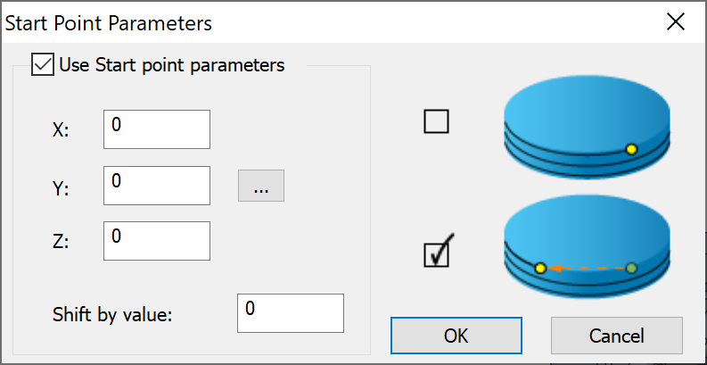
You can define the start
point by specifying the coordinates of the position. When you click ![]() , the Select point dialog box
is displayed with the coordinates of the point you pick on the model.
The coordinates of the selected point are displayed in the X, Y and Z
edit boxes.
, the Select point dialog box
is displayed with the coordinates of the point you pick on the model.
The coordinates of the selected point are displayed in the X, Y and Z
edit boxes.
The selected start point is applied to the first cut. For the subsequent cuts, you can define the start point using Shift by value. This option enables you to start the next cut at a specified distance from the previous start point. The distance defined in this field is measured along the path.
|
If the defined start point position is not located on the drive surface, SolidCAM automatically determines the closest point on the drive surface and uses it as the start point. |
Limits
The limits are the highest and lowest Z-positions for the tool – the range in which it can move. You can set the limits By target or By stock.
- Z-Top limit- This parameter defines the upper machining level. The default value is automatically determined at the highest point of the model.
- Z-Bottom limit- This parameter enables you to define the lower Z-level of the machining. The default value is automatically set at the lowest point of the model.
This limit is used to limit the passes to level ranges or to prevent the tool from falling indefinitely if it moved off the edges of the model surface.
When the tool moves off the surface, it continues at the Z-Bottom limit and falls no further.
Delta- This parameter allows you to set a value for machining above or below the values specified in Z-Top and Z-Bottom limits.
Cut tolerance
The Cut tolerance parameter defines the tool path accuracy. This parameter defines the chordal deviation between the machining surface and the tool path; the tool path can deviate from the surface in the range defined by the Cut tolerance.
You can type the value manually or adjust it using the slider.
A smaller Cut tolerance value gives you more tool path points on the drive surface resulting in more accurately generated tool path. The result is a better surface quality, but the calculation time is increased.
A larger Cut tolerance value generates less points on the tool path. After the machining, the surface finish quality is lower but the calculation is much faster.