CoordSys Data dialog box
Double-click CoordSys Manager in the CAM tree. The CoordSys Manager dialog box is displayed. Click Edit to view the CoordSys Data dialog box shown below.
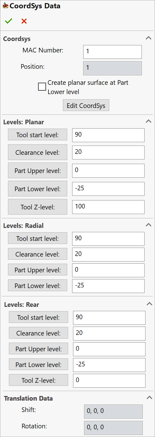
Coordsys
- MAC Number defines the number of the Coordinate System in the CNC-Machine. The default value is 1. If you use another number, the GCode file will contain the G-function that tells the machine to use the specified number stored in the controller of your machine.
- Position defines the sequential number of the Coordinate System.
Edit CoordSys enables you to change the CoordSys location or orientation of the axes with the CoordSys dialog box.
Create planar surface at Part Lower level
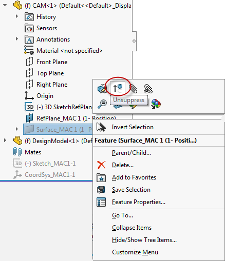
This option enables you to generate a transparent
planar surface at the minimal Z-level of the part so that its lower level
plane is visible. This planar
surface provides you the possibility to select points that do not lie
on the model entities. It is suppressed by default and not visible until
you unsuppress it in the FeatureManager Design tree. To unsuppress the
feature, right-click on its entry under the CAM component in the FeatureManager
Design tree and click the Unsuppress ![]() button.
button.
|
This option is available only when the Coordinate System has been defined by selecting a face. |
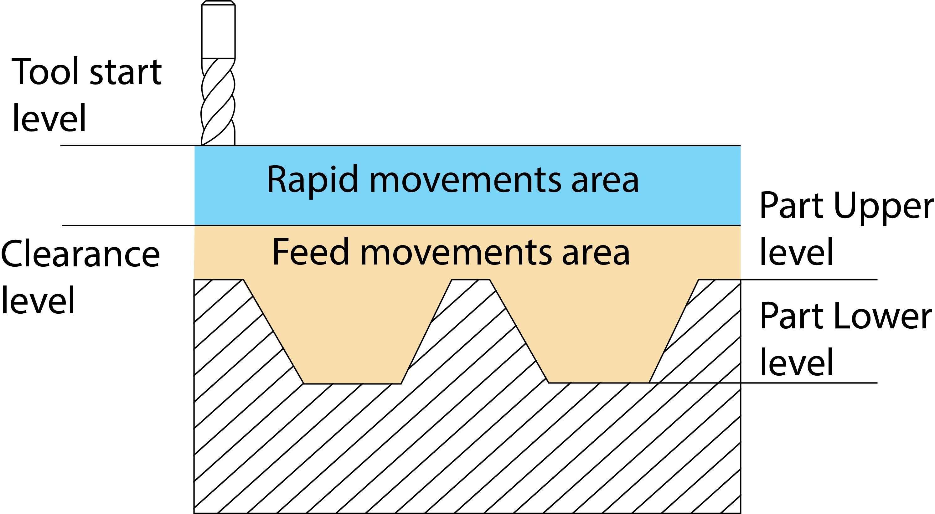
Levels
In the Milling module, facial and radial milling is performed using the same Coordinate System. But since the part levels used for facial milling are measured along the Z-axis, whereas those used for radial milling are measured around the Z-axis, the CoordSys data must be defined separately.
The Planar and Rear sections contain sets of facial machining levels describing the planes parallel to the XY-plane and located along the Z-axis.
Levels: Planar section displays levels for milling from the positive Z-direction.
Levels: Radial section contains a set of machining levels describing the virtual cylinders situated around the Z-axis.
Levels: Rear section displays levels for milling from the negative Z-direction. The negative Z-direction can be used in case of milling of the part from the back side with the same Coordinate System in the main spindle or in case of using the back spindle.
These sections contain the following parameters:
- Tool start level defines the Z-level at which the tool starts.
- Clearance level is the Z-level to which the tool rapidly travels when moving from one operation to another (in case the tool does not change).
- Part Upper level defines the height of the upper surface of the part to be milled.
- Part Lower level defines the lower surface level of the part to be milled.
- Tool Z-level is the height that the tool moves to before the rotation of the 4/5 axes to avoid collision between the tool and the workpiece. This level is related to the CoordSys position and you have to check if it is not over the limit switch of the machine. It is highly recommended to send the tool to the reference point or to a point related to the reference point.
Translation Data
Shift is the distance along each axis (X, Y, Z) from the Machine Coordinate System (Mac CoordSys) to the location of the Position in the coordinate system and the orientation of the Machine CoordSys.
- Rotation is the angle of rotation around the main axes X, Y and Z.
|
For the first Position number related to a new Mac CoordSys number, the Shift and Rotation parameters are always 0. Shift and Rotation for other Position Numbers related to the same Mac CoordSys number are determined automatically. |
Plane
The Plane box defines the default work plane for the operations using this CoordSys, as it is output to the GCode program. In the SolidCAM CAM module, you must always work on the XY-plane. Some CNC-machines, however, have different axes definitions and require a GCode output with rotated XY-planes. Choose one of the following options:
XY - the XY-plane is the work plane; the Z-axis is the depth (G17).
YZ - the YZ-plane is the work plane; the X-axis is the depth (G18).
ZX - the ZX-plane is the work plane; the Y-axis is the depth (G19).
|
This option works correctly only when your post-processor has been customized to support this function. Please contact customer support for further details. |
Related Topics