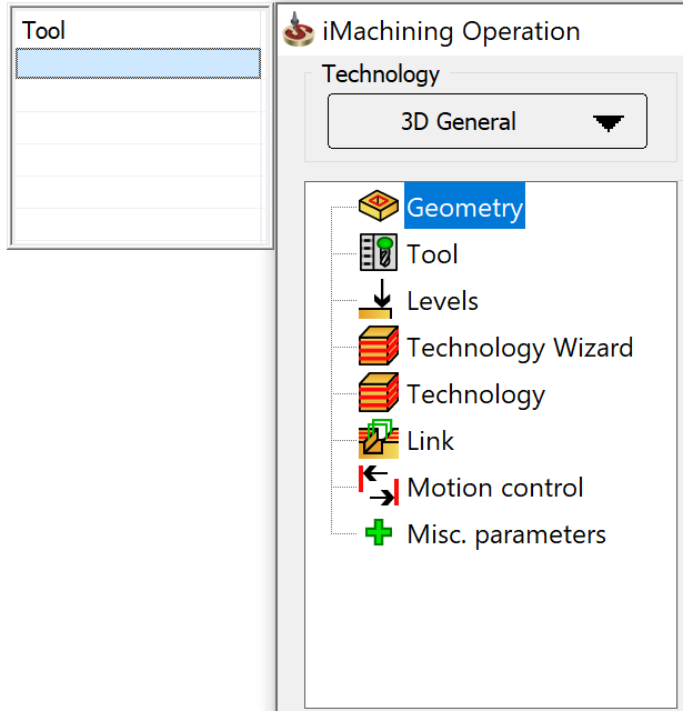
iMachining 3D Technology types
The specified Technology type determines the functionality of an iMachining 3D Operation, the availability of certain parameters and options as well as the resulting tool path.
Currently, iMachining 3D provides a complete machining solution for all your parts when combined with other SolidCAM technologies such as 3D HSM for finishing molds and complex 3D parts or iMachining 2D for finishing 3D prismatic parts.
iMachining 3D enables you to define the technological parameters used for calculation of the tool path passes. Using the proven algorithms of iMachining 2D and intelligent localized machining, roughing tool paths are generated first with deep Step down passes.

After achieving the final reachable depth (by the current tool) of the current region, rest roughing tool paths are then generated in Step-up mode to remove all rest material on sloped surfaces of general shaped 3D parts (3D General) or on higher horizontal surfaces of 3D prismatic parts (3D Prismatic).

During the Step-up process, the axial depth of cut gets smaller and usually varies every time a new higher step is machined. Although the depth of cut changes, previous versions of SolidCAM used the selected set of Cutting conditions for not only the Step down passes but also the Step-up passes.
|
|
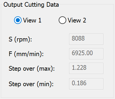
Output Cutting Data View 1 |
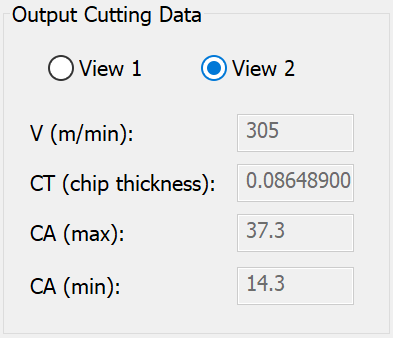
Output Cutting Data View 2 |
As described below, the Step-up tool path passes are managed differently according to the specified iMachining 3D Technology type.
3D General (default type)
Using the iMachining Operation dialog box, the 3D General technology enables you to define a roughing, rest machining and semi-finishing operation for general shaped 3D parts.
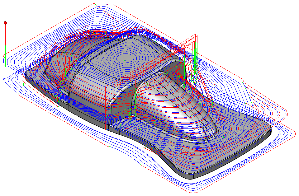
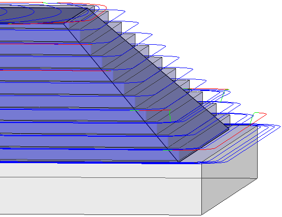
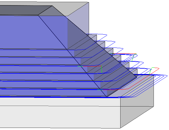
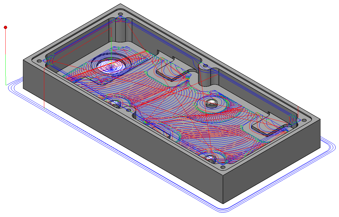
The example below illustrates a typical iMachining 3D General tool path.
The 3D General technology includes the following distinctions:
3D General Rest Rough (Step-up) – this mode is enabled by default and informs the iMachining technology to generate Step-up cutting passes by way of thin horizontal slices, creating a staircase-like effect on sloped surfaces.
Type
iMachining 3D enables you to choose the type of rest roughing tool path passes when using the 3D General technology. The Step-up height is dependent upon the specified Type.
Scallop (default selection)
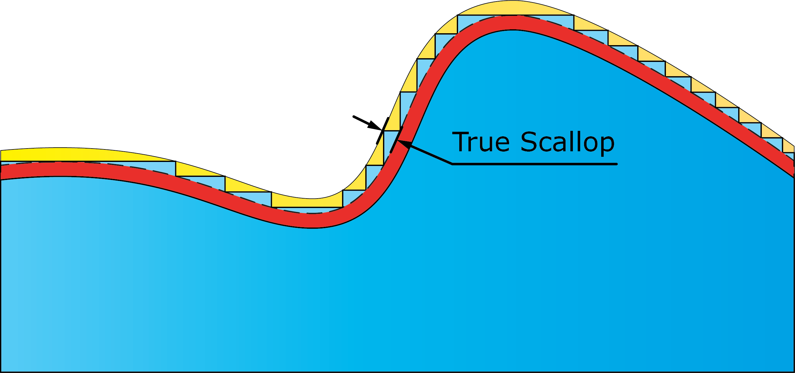
When this type is selected, the Scallop parameter defines the distance to the peak of all steps on slopes that are measured perpendicularly from the machining surface. The default value is calculated automatically according to the tool diameter.
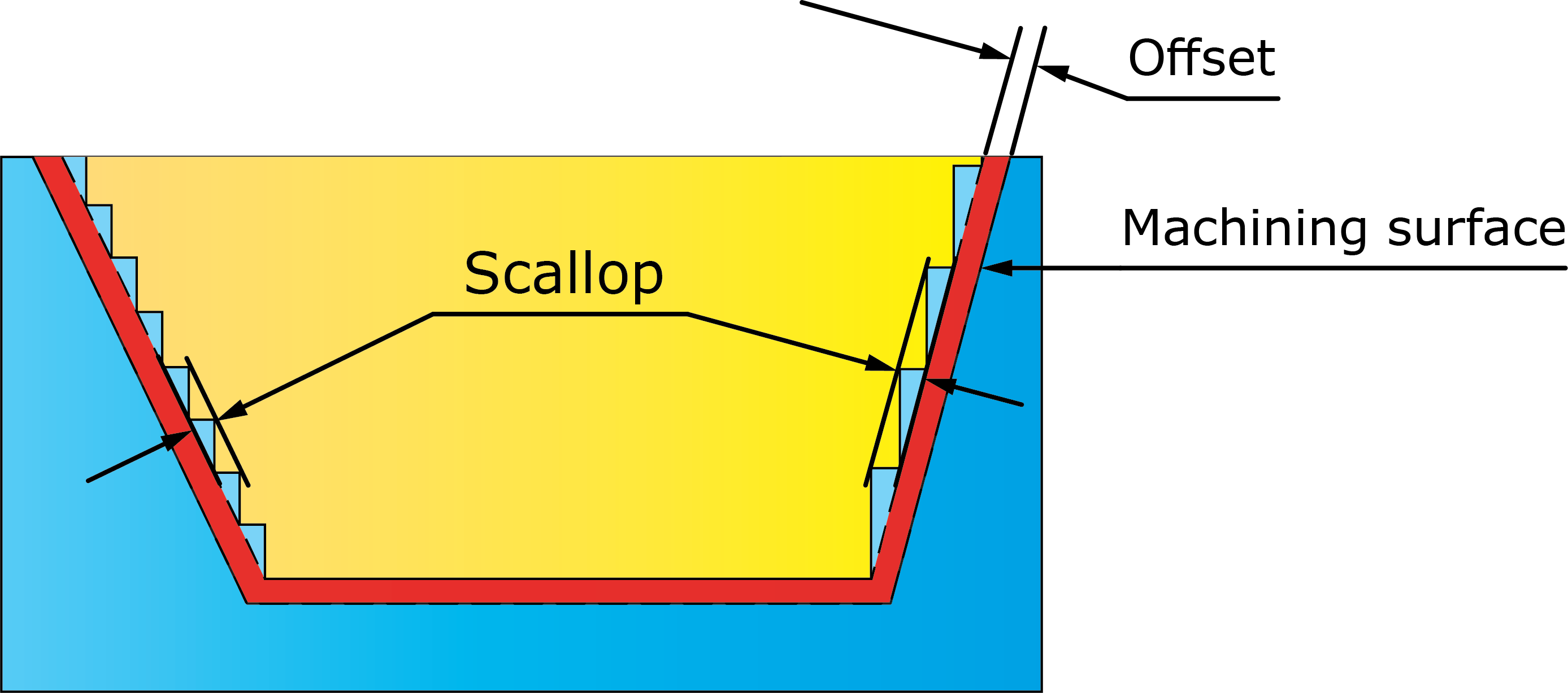
According to the local slope of each individual surface, the Step-up height changes dynamically in order to maintain the specified value throughout the operation. Every Scallop produced is therefore a True Scallop.
The Scallop parameter enables iMachining 3D to achieve its minimum machining feature on sloped surfaces. This feature restricts the rest roughing tool paths at any Z-level to only cut material that, if left uncut, would exceed the specified value.
|
Using the override check box and specifying a smaller value will result in finer passes, which can help avoid semi-finishing operations. However, the calculation time and cycle time will be proportionately longer. |
The minimum machining feature that is unique to iMachining 3D results in the following three benefits:
The total cutting length of the tool path is reduced, resulting in reduced tool and machine wear and further reduced cycle time.
A much more even amount of material is left on the slopes, making the subsequent finishing operations (using the HSM module) able to run faster with less tool load variations. Tool and machine wear and cycle time are reduced even further.
During the Step-up procedure, the axial depth of cut gets smaller every time a new higher step is machined. As the smaller depths are machined, the iMachining Technology Wizard increases the feed rate and cutting angle to maintain a constant load on the tool. As a result, the machining time of each higher step is shorter.
Scallop tolerance
The Scallop tolerance works in conjunction with the Scallop value and is an important parameter used for calculation of the Step-up tool path passes. The following two options are available for selection:
30% (default selection)
10%
This tolerance is applied to the specified Scallop value. It enables iMachining 3D to join two steps on two adjoining slopes, which would otherwise be cut at slightly different Z-levels, and perform one long cut at the same Z-level.
|
The effect of the default tolerance is to produce an actual scallop that may be up to 30% larger than the specified Scallop value. The total tool path length and cycle time will be appreciably shorter. |
Max. Cutting Angle
With each higher step-up, iMachining automatically increases the Cutting angle as the axial depth of cut gets smaller. The Max Cutting Angle option enables you to override the maximum default value for the operation. The Max Cutting Angle provided as default by the iMachining Technology is 800 degree for soft materials and 450 degrees for hard materials. It is recommended not to increase the Max Cutting Angle more than the given default value. On reducing the default Max cutting Angle, we can see on the uppermost step that along with the reduced Max Cutting Angle we also get a smaller step over range.
When this option is enabled, the iMachining 3D Step-up cutting passes are limited to the depths having ≥ 1.0 ACP. The value in the corresponding field reflects the Step-up depth equivalent to 1.0 ACP. Any depth less than the displayed value will be avoided.
|
|
Limit depth to one ACP Off |
Limit depth to one ACP On |
|
Limiting the Step-up depth enables you to match a more suitable tool with the remaining depth, thus avoiding vibrations otherwise caused by possible situations of instability. |
Constant
When this type is selected, the Constant parameter defines the vertical distance of all steps, regardless of the local slope of each individual surface (steep or shallow). The default value is calculated automatically according to the tool diameter.

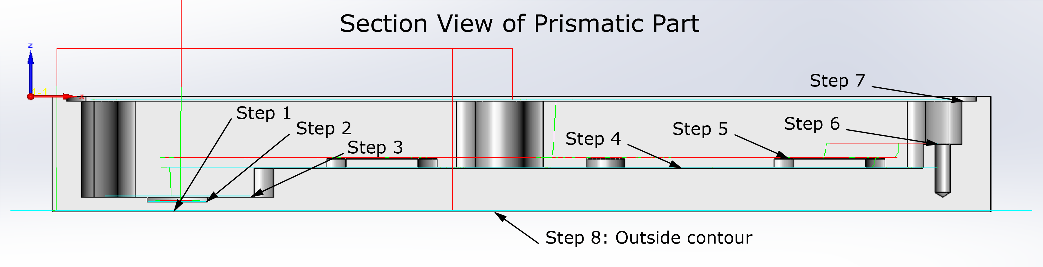
3D Prismatic
Using the iMachining Operation dialog box, the 3D Prismatic technology enables you to define a roughing, rest machining and semi-finishing operation for 3D prismatic parts.
The example below illustrates a typical iMachining 3D Prismatic tool path.
The 3D Prismatic technology includes only one distinction:
3D Prismatic Rest Rough (Step-up) – this mode is enabled by default and informs the iMachining technology to generate Step-up cutting passes on higher horizontal surfaces.
When machining 3D prismatic parts, performance and efficiency is automatically maximized to achieve the shortest possible cycle time. Even using iMachining 3D over iMachining 2D provides the following four benefits:
iMachining 3D performs the deepest step downs first to remove the most amount material, resulting in optimized depths of cut. Material Removal Rate (MRR) and tool life are maximized and the need for full retracts is eliminated.
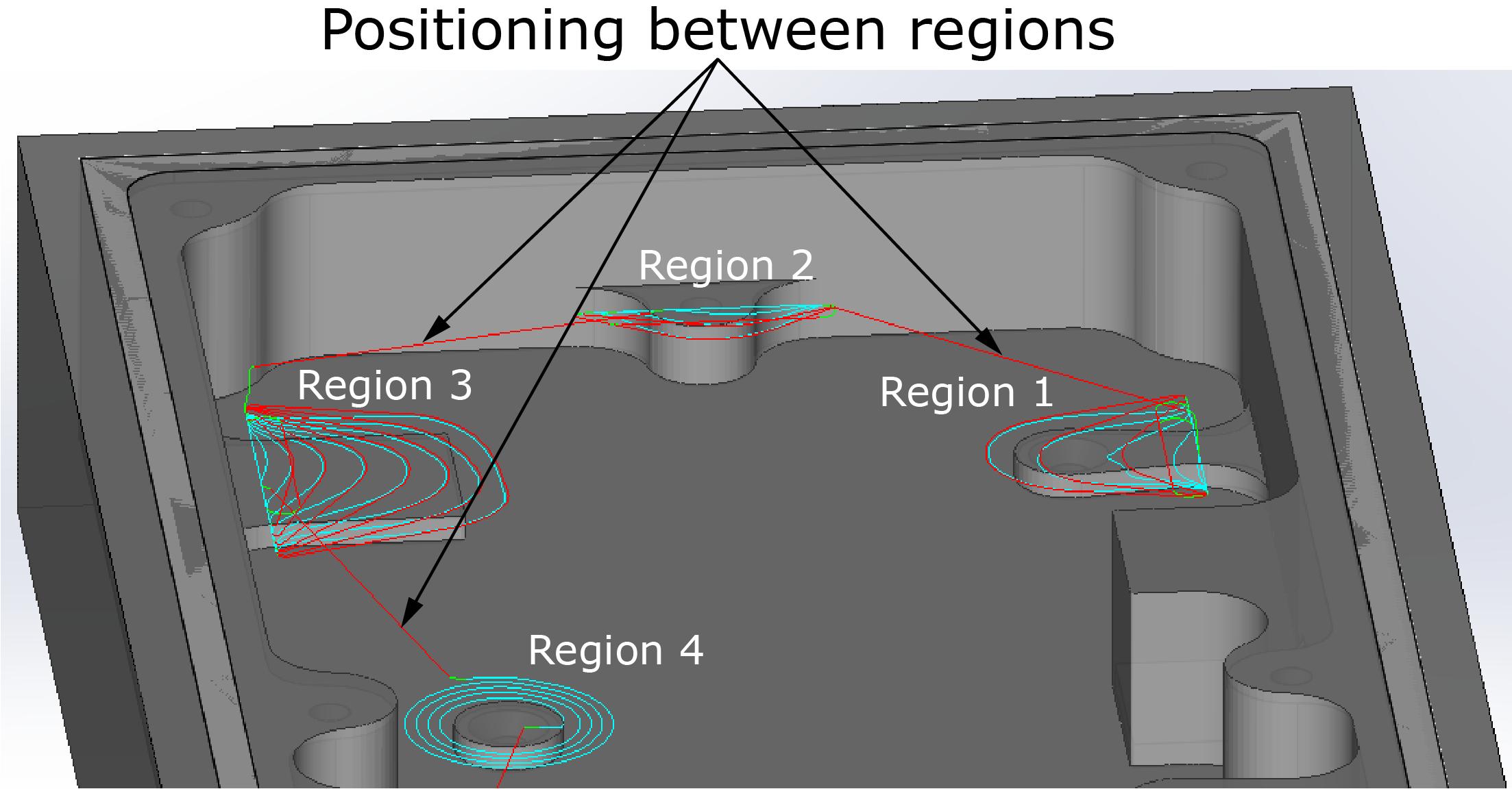
iMachining 3D performs intelligent sorting of 2D Z-level regions. Non-cutting moves are reduced by the 3D Z-level ordering and localized machining of 2D tool path regions.

iMachining 3D performs smart positioning between 2D Z-level regions. Long position moves are reduced by the 3D Z-level linking and localized machining of 2D tool path regions.
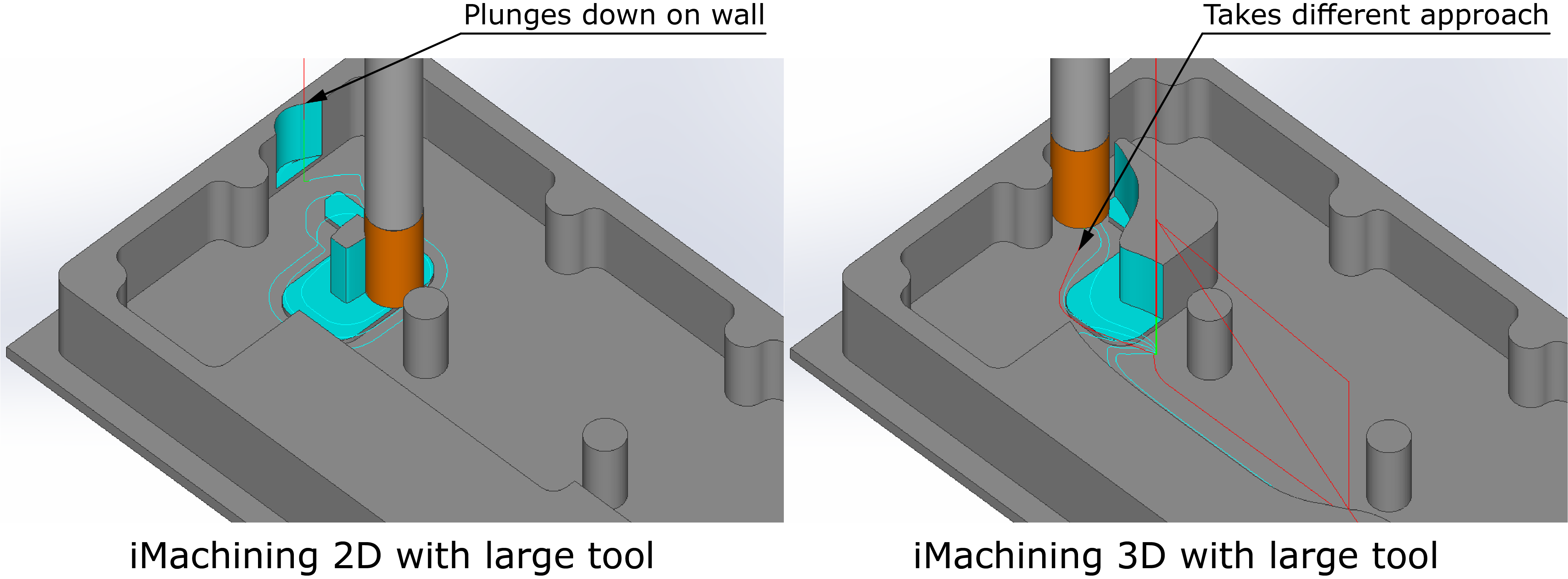
iMachining 3D provides automatic protection of the Target model. Large tools can safely be used in confined spaces.
Multi-tool operations
iMachining 3D generates tool paths according to the proven algorithms of iMachining 2D and the Technology Wizard. For that reason, most of the parameters and options appearing in the iMachining Operation dialog box for iMachining 2D are shared with iMachining 3D.
Whether you are using 3D General or 3D Prismatic, both technologies enable you to define multiple tools.
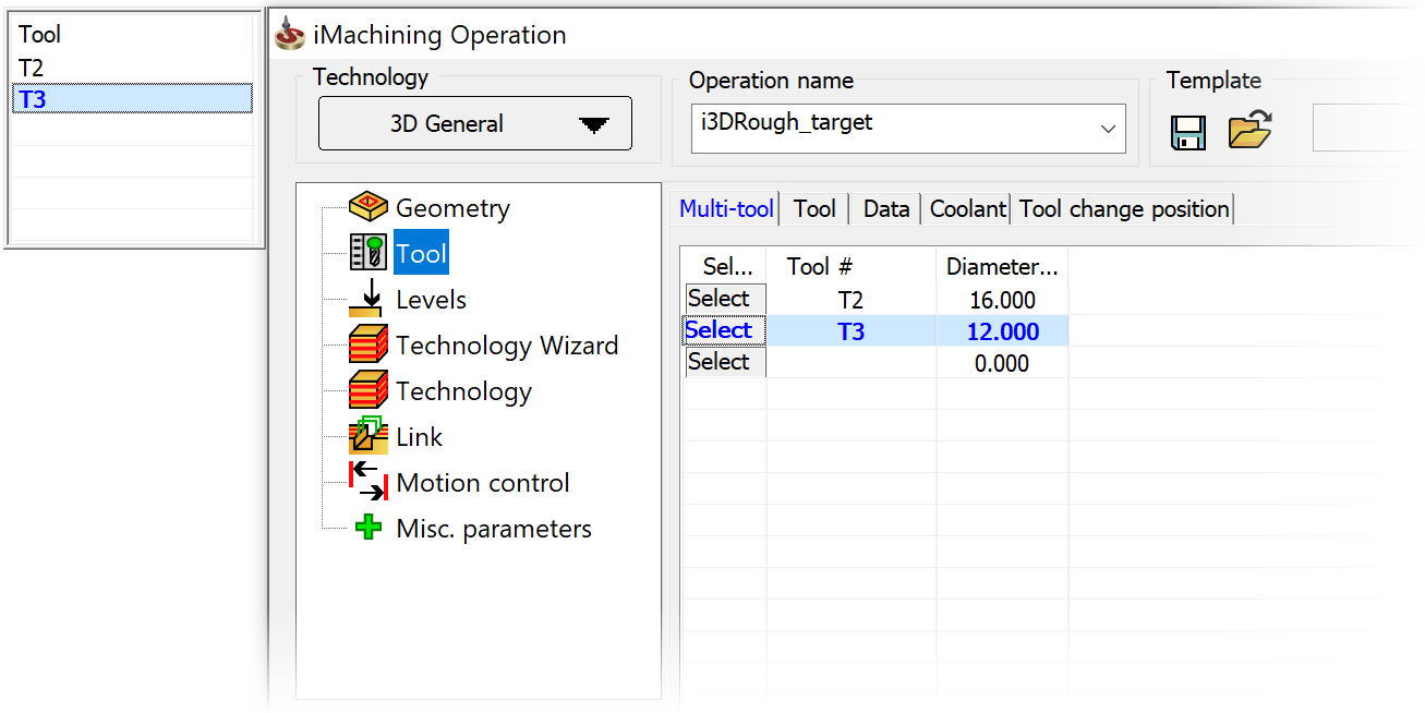
|
The Multi-tool interface features are the same with only one difference. The Finish Wall and Finish Floor options are not available for selection because finishing is currently not supported in iMachining 3D operations. |
While the Multi-tool functionality is always active and its interface features are always visible in the iMachining Operation dialog box, you are not required to use it. You can choose to:
1. Define a single machining task using just one tool.
Or from within a single interface
2. Using the 3D General technology (for general shaped 3D parts), define a sequence of related roughing, rest machining and semi-finishing tasks that use multiple tools.
3. Using the 3D Prismatic technology (for 3D prismatic parts), define a sequence of related roughing and rest machining tasks that use multiple tools.