iMachining – Multi-tool examples
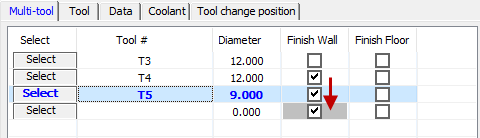
In the example below, the Tool definition contains three tools to perform the rough and finish machining of the outside contour of a bracket.
|
In iMachining Multi-tool operations, every tool performs the roughing or rest roughing plus the selected finishing option(s). |
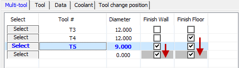
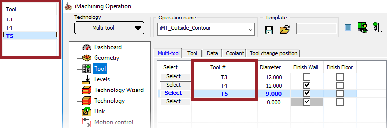 The tools in the Tool grid represent a group of sequential
machining tasks (or related operations) that together make up the Multi-tool
operation.
The tools in the Tool grid represent a group of sequential
machining tasks (or related operations) that together make up the Multi-tool
operation.
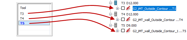
Tools in Multi-tooloperation |
Resulting related operations |
 |
|
|
When later saving/saving and calculating, the related operations will appear separately in the CAM tree. |
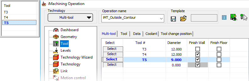
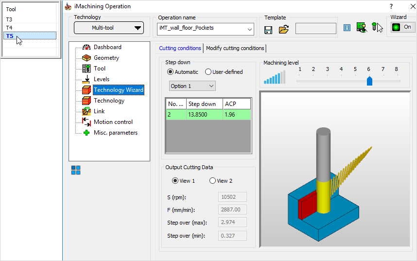
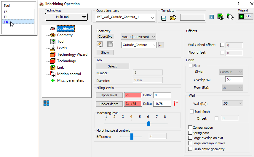 The data shown in the iMachining Operation interface
corresponds to the currently selected tool in the Tool grid.
Data management and
associativity
The Multi-tool technology shares and manages common
data (i.e., Geometry and Levels selections) between the related operations.
When common data is modified in one operation, it is automatically synchronized
across all other operations.
The data shown in the iMachining Operation interface
corresponds to the currently selected tool in the Tool grid.
Data management and
associativity
The Multi-tool technology shares and manages common
data (i.e., Geometry and Levels selections) between the related operations.
When common data is modified in one operation, it is automatically synchronized
across all other operations.
|
When specifying Delta depths, like in the case of machining outside contours and you want the Multi-tool operation to cut deeper than the part bottom edge, it is recommended to make the Levels selections and enter the Delta depth value(s) prior to defining the tools. If not, the Delta depth entries will have to be repeated for each of the related operations. |
1. If any settings are modified in a preceding operation, subsequent operations are updated automatically.
Upon recalculation, all operations are recalculated in sequence.
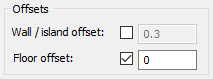
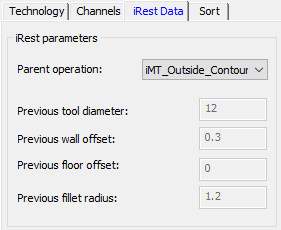
2. Offsets are inherited from preceding operations and the iRest Data of subsequent operations are managed automatically.
| 1st Tool |
|
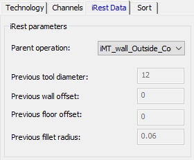
| 2nd Tool |
|
| 3rd Tool |
|
3. All air cutting is eliminated by automatic detection and allocation of cutting technologies from operation to operation.
Example
1:
 |
|
| 1st Tool | 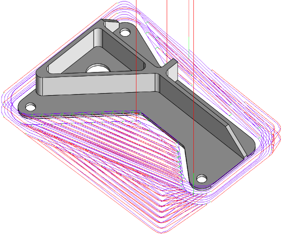 |
| 2nd Tool | 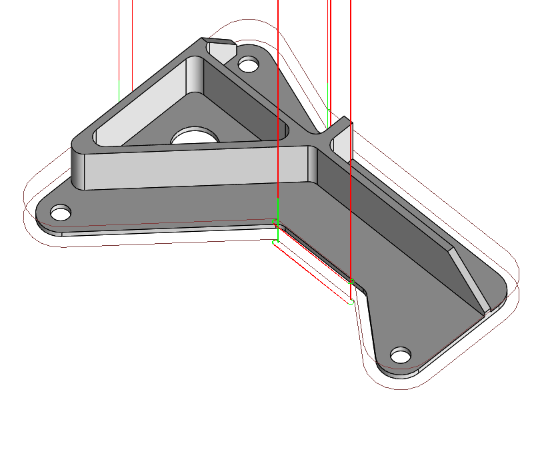 |
| 3rd Tool |  |
Example
2:
 |
|
| 1st Tool | 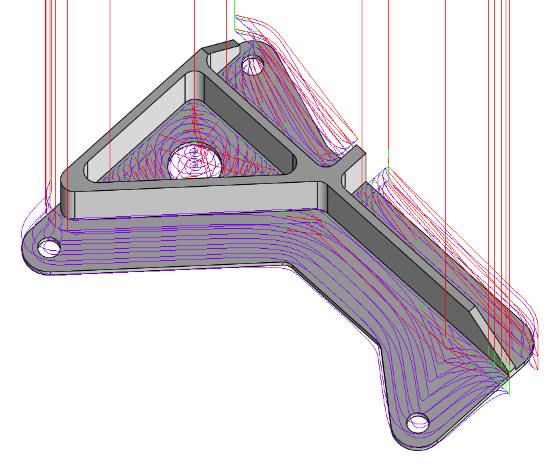 |
| 2nd Tool | 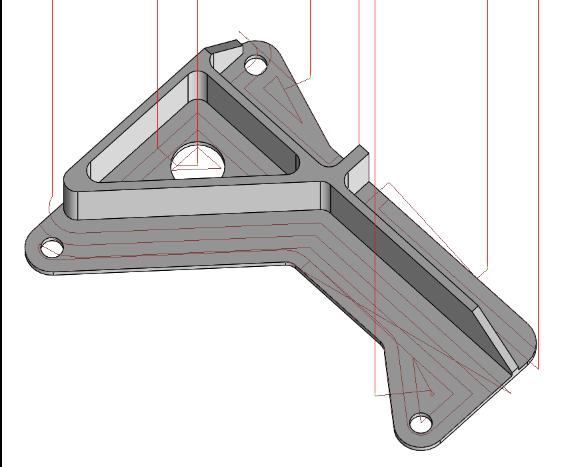 |
| 3rd Tool | 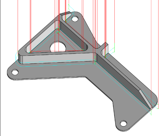 |
In both examples above, the tool path is automatically optimized and no time is wasted on areas already machined.
As with any other iMachining operation (iRough, iRough + iFinish, etc.) in SolidCAM, the requirements for defining a Multi-tool operation are minimal. Once the Geometry, Tool and Levels definitions are completed, you can simply use the default values calculated for all other parameters.
The Technology Wizard also provides for each tool, as each tool represents a separate but related operation, Cutting conditions that are optimal. By switching to the Technology Wizard page and toggling through the tools in the Tool grid, you can view the Cutting conditions specific to each tool.
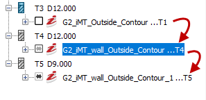
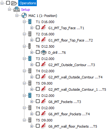
The example below is a CAM tree view of the related operations resulting from just three Multi-tool operations defined, saved and calculated.
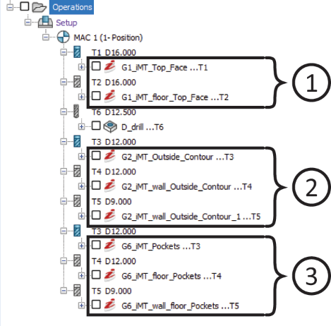
To further increase productivity, you can even change/rearrange operations in the CAM tree according to tool sequence. Doing so can help save time that would otherwise be spent on unnecessary tool changes.
 |
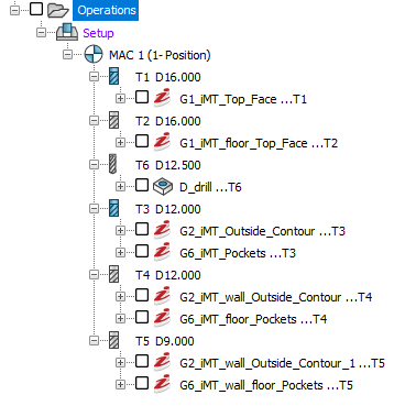 |
Before |
After |
|
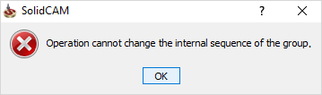
A Multi-tool operation contains internal sequences and data dependencies that must be preserved. As a result, SolidCAM does not permit from the CAM tree the reordering of related operations in a way that will break the internal sequence.
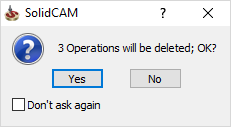
Nor can you delete any one related operation that breaks the dependency of data to another; upon deleting one, SolidCAM will prompt you to delete all.
|