Chip Load vs. Chip Thickness
In iMachining operations, there is a distinct difference between chip load and chip thickness as described below.
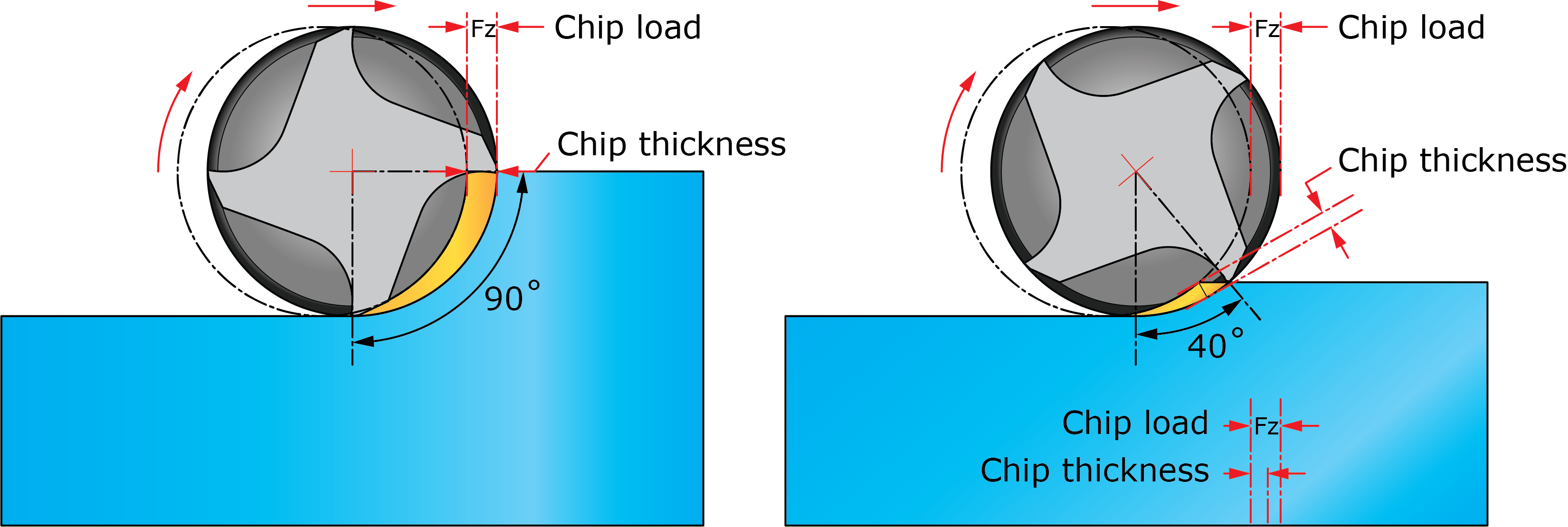
Chip Load
Not to be confused with chip thickness, chip load defines the feed rate of the tool, measured in units of distance per tooth. The FZ values can be viewed on the Data tab of the Tool page.
Chip Thickness
Chip thickness (CT) can be described as the thickness (at the widest point) of the undeformed chip that is sheared away from the material. The CT value for the operation appears in View 2 of the Output Cutting Data on the Technology Wizard page.
Relationship between chip load and chip thickness
Traditionally, the only instance where you would see equal values of chip load and chip thickness is when the cutting angle is at 90°. Anything less than 90° will inherently produce a chip that is thinner than the specified chip load, resulting in uncontrolled tool load variations.
In iMachining calculations however, morphing spiral tool paths are generated according to a dynamically varying cutting angle that can range anywhere between 10° and 80° depending on the selected Machining level. To compensate for the dynamically varying cutting angle, the Technology Wizard automatically adjusts the feed at every point along the tool path in order to maintain the specified chip thickness, which is matched to the original chip load as shown below.
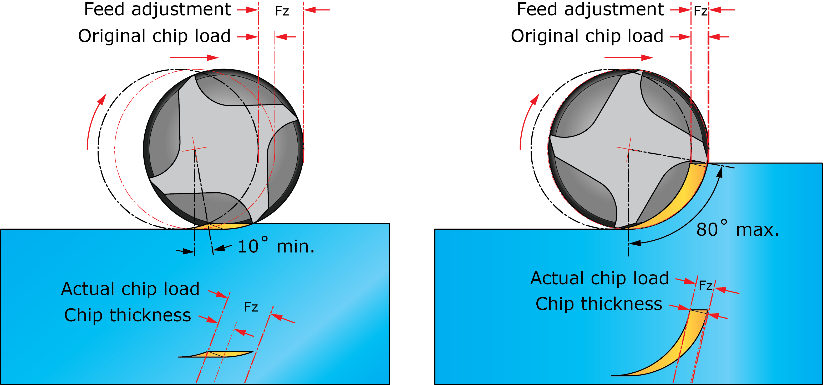
By the automatic synchronization of these and other values, the Cutting conditions always remain optimal to achieve a constant load on the tool.