Submachines
The Submachines folder enables you to define and manage the active Tool-Part cutting pairs of the CNC-Machine.
One Submachine is always included in the Machine Definition by default.
In a Mill-Turn machine having one turret and two spindles, you can define two Submachines:
- First Tool-Part cutting pair: Turret and Left Spindle
- Second Tool-Part cutting pair: Turret and Right Spindle
To add a new Submachine, right-click the Submachines folder in the Machine tree and choose Add Submachine from the menu.
Submachine Main Parameters
The main parameters of the Submachine definition are as follows:
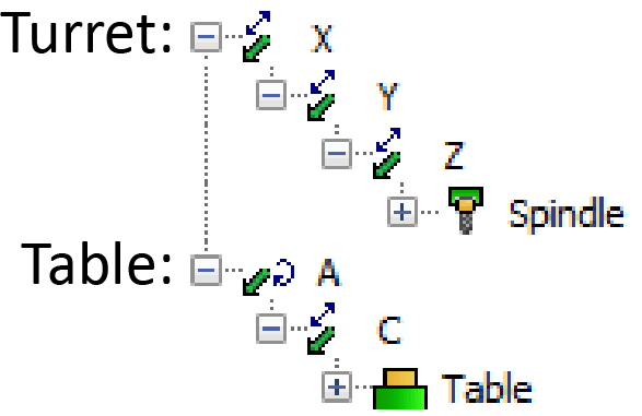
| Turret Name | Choose the Turret name from the list of available turrets. |
| Table Name | Choose the Table name from the list of available tables. |
| Name | Enter the Submachine name. |
| Operation Type | Choose the type of operations you are going to perform with the submachine: • MILLING • TURNING • MILLING and TURNING |
| Max Inverse Time Feed | Enter the Maximum Inverse Time Feed. |
| M.R.Z. Point | Theoretical intersection point between two rotary axes or Machine Rotation Zero Point is a point according to which you get the RPOS coordinates. This point is calculated automatically relative to the Machine Coordinate System and according to certain rules. |
| First Angle Pair Interval (deg) | Enter the First Angle Pair Interval. |
| CoordSys | Double-click the Value field to manage the CoordSys parameters of the submachine. |
| Axes Order | Double-click the Value field to manage the Axes Order parameters of the submachine. |
Coordsys
Each row of the CoordSys parameters enable you to define the vector orientation of the corresponding coordinate system axis.
X Vector
|
Choose the value
from the list or select |
Y Vector |
Choose
the value from the list or select |
Z Vector
|
Choose
the value from the list or select |
Like the main devices, select/define the X Vector, Y Vector and Z Vector coordinates using the Value fields. These vectors are relevant to the machine’s X-, Y-, Z-Axis vectors. You can also define values around generic coordinate system axes in Rotation Around (deg) field.
CoordSys vector orientation affects the output of tool path coordinates in GCode generation.
The Position is defined automatically and cannot be changed.
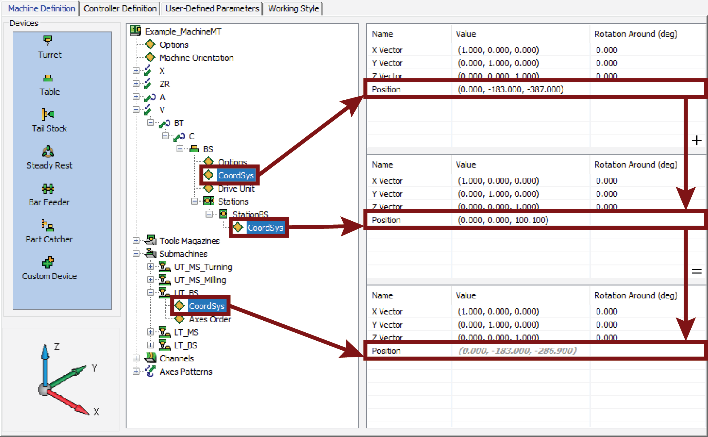
As shown in the above picture, the Position is calculated according to:
The chosen Table in Submachine
plus
The Table Station position (relative to Table CoordSys)
Axes Order
The Axes Order is defined by the following parameters:
Used in Milling As
|
Choose the type of movements you are going to perform with the axis in Milling operations: • SIMULTANEOUS • INDEXIAL • NOT USED |
Used in Turning As |
Choose the type of movements you are going to perform with the axis in Turning operations. For Linear axes, the choices are the same as those used in Milling operations. For Rotary axes, the choices are: • INDEXIAL • NOT USED |
Inclined Turning
|
Choose whether or not the axis can perform simultaneous tilting movements in Turning operations: • TRUE • FALSE |
The order for Rotary axes is determined by the rules related to the kinematic configuration of the CNC-Machine.
The following rules apply to the Axes Order:
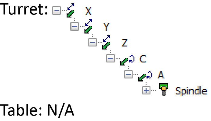
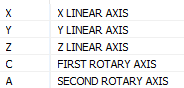
| Head-Head | For
Head-Head machines, the dependent axis is the second rotary axis.
 Axes Order
|
||
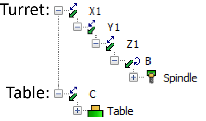
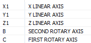
| Head-Table | For Head-Table machines,
the first rotary axis should be located on the table.
.png) Axes Order
Axes Order
|
||
| Table-Table | For
Table-Table machines, the dependent axis is the first rotary axis.
 Axes Order
|
All operations are calculated according to the order (priority) defined for the Axes Order.
If the axis value is left blank as shown in the picture below, the axis will be inactive in the current Submachine.
![]()
In this example, one Rotary and one Linear axis are inactive, which means that only the remaining axes can be moved.
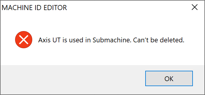
In order to delete an axis, it first has to be made inactive in the Axes Order. Only then will you be able to delete the axis. If you otherwise try to delete an axis that is active, the error message is displayed: