CAM-tree
This page enables you to define how the CAM-tree looks.
The View tab contains the following options:
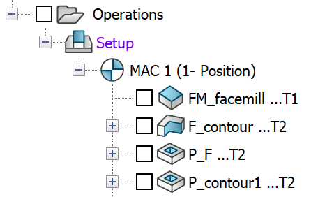
CAM-tree view
In the View options section, you can toggle between showing and hiding tools, CoordSys, tool positioning, tool number, operation number, Submachine, drilling cycles, machining time, compensation usage and other elements in the CAM-tree.
Show tool image
This section enables you to define which tool parameters are shown in the CAM-tree, when the Show tools image is chosen.
You can show or hide the following parameters:
- Type
- Description
- ID number
- Diameter (for milling tools)
- Offset number
- Tool number
- Turret/Station/Position
Indent According to...
The Indent according to section enables you to select the first level for setting in the operations in the CAM-tree.
|
Both CoordSys and Tools options have to be selected to enable choosing of the indentation option. |
Apply those options while opening all CAM-Parts enables you to choose the viewing options for all CAM-Parts.
Operation name in CAM Manager
The setting of this field defines how the operation names appear in CAM Manager when a Machining Process Table is loaded and a Machining Process is added to the CAM-Part.
When the Show group name check box is selected, the operation names are preceded with the names of the operation groups and default sets defined in Machining Process Table Manager.

When this check box is not selected, only the operation names appear in the CAM Manager tree.
Font Colors
The Font Colors tab enables you to change the operation appearance in the CAM-tree interface. You can choose bold or italic typeface and select the color for the operation name.