Fixture definition - Chuck (Standard)
This option enables you to define a standard three-step chuck by specifying the clamping method, chuck position and dimensions.
Clamping method and position
The Clamping method section enables you to define how the clamping device will be attached to the workpiece. The Mirrored option enables you to toggle between locations and orientations of the current fixture.
The following clamping methods are available:
![]()
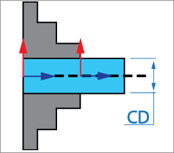
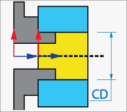
When this option is chosen, the part is clamped by its external face with the inner faces of the jaws.
The chuck positioning is defined with the Clamping diameter (CD).
|
 |
![]()
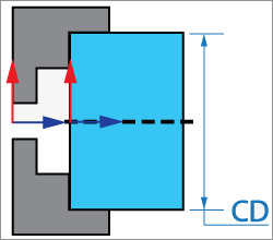
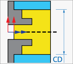
When this option is chosen, the part is clamped by its external face with the first step faces of the jaws.
The chuck positioning is defined with the Clamping diameter (CD).
|
 |
![]()
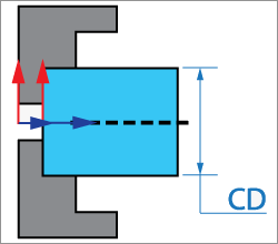
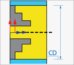
When this option is chosen, the part is clamped by its external face with the second step faces of the jaws.
The chuck positioning is defined with the Clamping diameter (CD).
|
 |
![]()
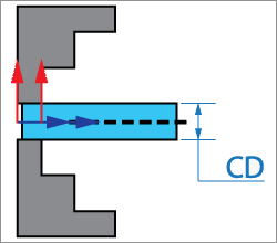
When this option is chosen, the part is clamped by its external face with the outer faces of the jaws.
The chuck positioning is defined with the Clamping diameter (CD).
|
 |
![]()
When this option is chosen, the part is clamped by its internal face with the first step faces of the jaws.
The chuck positioning is defined with the Clamping diameter (CD).
|
 |
![]()
When this option is chosen, the part is clamped by its internal face with the second step faces of the jaws.
The chuck positioning is defined with the Clamping diameter (CD).
|
 |
![]()
When this option is chosen, the part is clamped by its internal face with the outer faces of the jaws.
The chuck positioning is defined with the Clamping diameter (CD).
|
 |
The Clamping diameter (CD) parameters can be defined by picking on the model. When the model is picked, SolidCAM measures the X- distance from the CoordSys origin to the picked position and displays the value in the corresponding edit box.
Chuck sizes library
The Take from library button enables you to import a fixture from the Fixtures library.
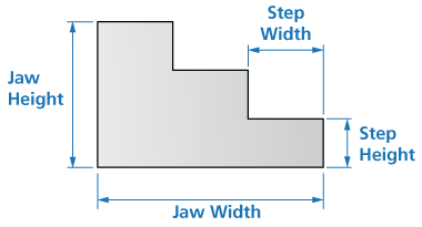
Jaws parameters
This section enables you to define the chuck geometry.
Jaw width (JW)
This parameter defines the overall width of a single jaw.
Jaw height (JH)
This parameter defines the overall height of a single jaw.
Step width (JW)
This parameter defines the width of the lower step.
Step height (SH)
This parameter defines the height of the lower step.
|
Associativity is not maintained for chucks defined by parameters. |
Visualization
The Suppress/Unsuppress stock envelope button toggles the visibility of the stock envelope sketch.