Tool axis control page
This page enables you to define the orientation of the tool axis during the Sim. Turning operation.
Tool axis direction
This section enables you to define the orientation of the tool axis during the machining relative to the surface normal.
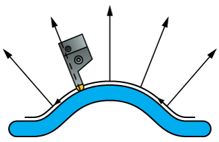
This option enables you to keep the tool axis direction coincident to the surface normal at the cutting position. In other words, the tool is always normal to the surfaces during the machining.
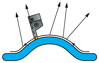
This option enables you to define the tool tilting by a number of lines. The tool axis is changed gradually along the tool path trying to pass through the defined lines.
The Tilt lines section enables you to choose the lines geometry from the list or define a new one with the Define button, using the Geometry Edit dialog box. The direction of the side tilting gradually changes, passing the defined tilt lines.
Interpolation
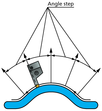
The Max. Angle step parameter enables you to define the maximal allowed angle change between the tool axes at two consecutive tool positions.
Decreasing the Max. Angle step value causes SolidCAM to generate more tool path points.
Angle range
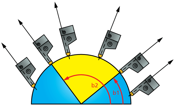
SolidCAM enables you to limit the tool tilting along the tool path. Click on the Limits button to define the angle range parameters.
The Limits dialog box is displayed.
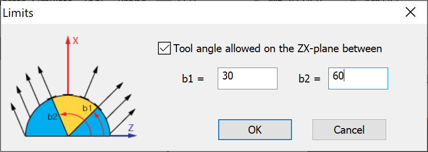
The Tool angle allowed on the ZX-plane between option enables you to limit the tool tilting by projecting the tool axis on the ZX-plane of the current Coordinate System. The b1 and b2 parameters define the start and end angle of the limit.