Working Style
The Working Style page enables you to define preprocessor settings and parameters used for operation default values and for software only.
The following global parameters are not related to a specific submachine or channel:
Parameter Name |
Description |
PRP Name |
Pos to Machine |
This parameter enables writing posts in the new style. SolidCAM provides GCode output for a number of coordinate systems. |
pos_to_machine |
DPP File Name |
Name of the *.dpp file used to customize the Documentation output. |
doc_processor_name |
Defines the tool table name of the machine to be the part tool table. |
tool_table_name |
|
The delta address of the offset table in the machine controller. Used for the Documentation option only. |
Delta_for_TOOL_H |
|
Home Data At Start |
Defines the location where the @home_data will be printed: either at the beginning of the program after @def_tool, or in the end of the program after @end_of_program. |
home_data_at_start |
At Start All Axes Set To Home Ref |
Determines if all axes are shown in Home Reference position for START PROGRAM item in the Move List Pane of Machine Simulation, when simulating the entire part. |
|
At End All Axes Set to Home Ref |
Determines if all axes are shown in Home Reference position for END PROGRAM item in the Move List Pane of Machine Simulation, when simulating the entire part. |
|
Safety Distance |
Defines a default value for the ‘safety_dist’ parameter used in the dialog boxes throughout various operations. |
safety_dist |
Hole Wizard (metric) |
Name of the Hole Wizard process for metric units (location is defined in SolidCAM Settings). |
|
Hole Wizard (inch) |
Name of the Hole Wizard process for inch units (location is defined in SolidCAM Settings). |
|
This page includes the following sections:
General
This section contains parameters related to the general settings. Set the required values in each submachine's column.
Compensation By Zero(Milling only) |
Indicates whether the tool-radius compensation is zero (Yes) or tool radius (No). |
comp_by_zero_tool |
Compensation Rough Passes (Milling only) |
Default value for Compensation Exists parameter on Rough Passes. |
- |
Compensation Finish Passes (Milling only) |
Default value for Compensation Exists parameter on Finish Passes. passes. |
- |
Compensation Clear Offset Passes (Milling only) |
Default value for Compensation Exists parameter on Clear Offset. |
- |
Compensation for Chamfer exists (Milling only) |
|
|
Arc Exist as Default (Milling only) |
Default value for Support Arcs parameter. |
arc_exist |
Software Transform |
Enables enhancements of the transformation feature. |
software_transform |
Finish Retreat (Turning only) |
Indicates whether the finish process of the machine cycle retreats to the start point (Yes) or remains at the last point (No). |
finish_retreat |
Semi-Finish Retreat (Turning only) |
Indicates whether the semi-finish process of the machine cycle retreats to the start point (Yes) or remains at the last point (No). |
semi_finish_retreat |
Allows whether or not cutter wear compensation can be used in the rough process of the machine cycle. |
|
|
Use Turning Cycle as Default |
Default value for Turning Cycle parameter. |
turning_cycle_dflt |
Use Groove Cycle as Default |
Default value for Groove Cycle parameter. |
groove_cycle_dflt |
Trace Output
This section enables you to customize data shown in the operation trace.
Tool Path Info for XY |
Tool path information for XY approach is shown in trace. |
-- |
Tool Path Info for Z |
Tool path information for Z approach is shown in trace. |
-- |
GCode Output
This section enables you to customize data related to the operation GCode. You can set the parameters separately for each channel.
Output GCode Channels |
Controls generation of GCode files for several turrets. Mixed on Single File – Generates separate GCode files for each turret and combines all files into the first GCode file. The first GCode file is the file generated for the first turret defined in Devices section of VMID. Separated Files – Generates separate GCode files for each turret. Order on Single File – Generates one GCode file that includes GCode of all operations in the order that operations are defined in CAM Manager. |
turret_channel |
Specifies the extension of the generated GCode file. |
gpp_file_ext |
|
GCode File Name Format |
Specifies the naming format of the generated GCode file. The GCode file can be named using the Part Name & Channel Name or using the Program Number & Channel Name. |
|
GCode File Name Max Length |
Specifies the maximum number of characters allowed in the GCode file name. |
max_g_name_length |
GCode Folder |
Specifies the name of the GCode folder. |
dir_gcode |
Allow Spaces in GCode File |
Allows whether or not spaces can be used in the GCode file name. |
|
Separate Folder For Each GCode File |
Creates a separate folder for each GCode file to which the GCode segment files are saved. |
split_gcode_folders |
Separate Folder For Each CAM-Part |
Creates a separate folder for each CAM-Part to which the GCode files are saved. |
gcode_part_subfolder |
Split Files Counter Separator |
Specifies the symbol to be used for separating the parts of the file name. |
split_gcode |
Skip Machine Limits Checking |
Specify whether or not to check machine limits in GCode generation. |
|
Program Numbers
This section enables you to define the default numbers assigned to the main program and subroutine. You can set the numbers separately for each channel.
Default Program Number |
Default program number. |
prog_num_dflt |
Default Procedure Number |
Default number for first procedure. |
proc_num_dflt |
Procedures
This section enables you to control different aspects related to procedures execution.
| Procedures | Indicates whether procedures can be generated in the GCode. |
gen_procs |
| Procedures in Drill | If several drilling operations have the same drill points, then the drill points are stored in a single separate procedure. |
drill_proc |
| Sub-Procedures | Indicates whether internal procedures of the operation will be generated. |
gen_internal_proc |
Numerate Procedures Separately for Every Split |
Defines that all GCode programs created in a part with splits have subroutines that start with the same number of the first block. |
same_sub_numbers |
Initialize GPP Variables Every Split |
All GPP variables will be initialized in every GCode program in part with splits. |
init_var_after_split |
Optimize Operations Loops |
Saves tool paths among continuous operations that have the same Edit operations. Used only for Milling. |
optimize_jobs_loop |
Loop Exist |
If “YES”, generates pcode @loop. Otherwise, instead of @loop, generates @change_ref_point for transformation and @rotate for rotation. |
loop_exist |
Procedures in Turning |
Defines whether to generate a separate procedure for geometruc points of a turning process, or the points will be generated immediately after the cycle. |
turn_proc |
Procedures in Combine Turning |
Generates a procedure of common geometric points for several cycles. |
turn_common_procs |
Procedures in Turning With Single line |
Specifies the GCode format if the cycle geometry is a single line. |
gen_single_line_proc |
Channel Synchronization
This section enables you to define row colors in Channel Synchronization for:
- Tables
- Turrets
- Axes
- Workpieces
- Machine Control Operations
- Stock Management Operations
All colors are represented by RGB values, which can be changed either
by manually entering decimal color codes or by choosing  in the Value
drop-down list. The latter option displays the standard Windows Color
selection dialog box that enables you to pick your preferred color.
in the Value
drop-down list. The latter option displays the standard Windows Color
selection dialog box that enables you to pick your preferred color.
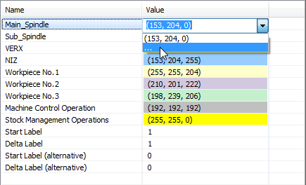
The Channel Synchronization section also enables you to define Start Label and Delta Label values.
iMachining
This section enables you to define a default machine and work material that is associated to the post-processor. When choosing the post-processor in the CAM-Part Definition, the default selections will appear automatically in the iMachining Data area of the Milling Part Data dialog box.
If there is no Default Material Database selection, that which is chosen in the SolidCAM Settings will be used.
Sim 5x Options
This section enables you to define advanced options for Sim. 5-axis operations.
| Auto Angle Pair | The postprocessor determines automatically which pair of angles to use. |
auto_angle_pair |
| Other Angle Pair | The second angle pair, other than the first automatically determined, is used. |
other_angle_pair |
| Start Angle Type | Type of start angle. |
start_angle_type |
Solution Type for Start Angle |
Type of solution for start angle. |
solution_for_start_ angle |
Preferred Start Angle |
Preferred start angle. |
start_angle |
Angle Tolerance for Using Machine Limits |
Angle tolerance for using machine limits. |
angle_tol_for_limits |
Interpolation for Distance |
Sets the interpolator for distance on and off. |
interplat_for_dist |
Enable Mx Edit |
Enable to change inside the 5-axis operation the value of the following two parameters: Auto Angle Pair and Other Angle Pair. |
enable_mx_edit |
Use Machine Limits |
Defines whether to use the machine limits in both translational and rotational axis. |
use_machine_limits |
Retract Distance |
Determines the retract distance of the tool from the part if a large angle change is detected based on the limit defined by angle change limit. |
retract_distance |
Interpolation Distance |
Sets the interpolation distance step in MLC. The postprocessor will interpolate between two tool tip positions (part coord.) using this threshold value. |
interplat_distance |
Angle Change Limit |
Angle change limit in degrees from one posted tool path position to the next one. |
angle_change_limit |
Interpolation Angle Step |
Interpolation angle step in degrees; the postprocessor will interpolate between posted tool path positions using this angle. |
interplat_angle_step |
Pole Angle Tolerance |
Defines the pole areas where the rotary axis and spindle direction are parallel. |
pole_angle_tolerance |
Timing
This section enables you to define options related to the time of machining.
| Time Factor | The tool path time calculated in the simulation process is multiplied by this factor. It is used to improve the accuracy of the work time calculations. |
time_factor |
| Block Time | This parameter determines the extra time (in seconds) of every movement block. It is added to every block in order to improve the accuracy of the work time calculation. |
block_time |