Gouge check page
SolidCAM enables you to define four different sets of gouge checking parameters. In each set you have to choose components of the tool holding system and model faces to check the possible collisions between them. You also have to define the strategy to avoid the possible collisions. Combining these sets, SolidCAM enables you to choose different strategies for avoiding the different types of possible collisions.
Select the Enable/Disable check box to activate a set of gouge checking parameters.
Tool
This section enables you to choose both tool and tool holder components to perform the gouge check for them.
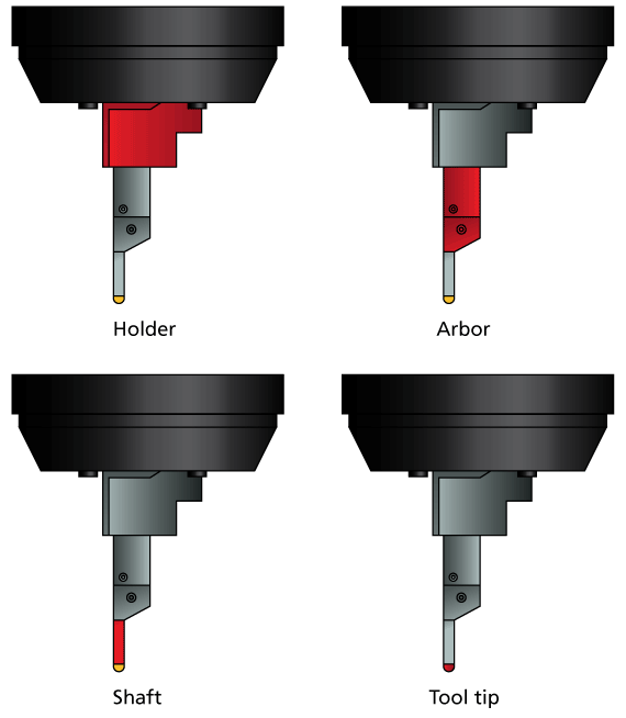
SolidCAM enables you to choose the following part of the tool and tool holding system to perform the gouge check:
Holder
Arbor
Tool tip
Tool shaft
Geometry
This section enables you to choose the model faces for which the gouge checking is performed.
The Check surfaces option enables you to choose a number of model surfaces not intended to be machined as the check surfaces and perform the gouge checking for them. You can choose the check surfaces geometry from the list or define a new one with the Define button displaying the Select Faces dialog box.
When the Use STL file check box is activated, the Check surfaces section enables you to choose a check surfaces geometry from an STL file. The Define button enables you to display the Choose STL dialog box.
The Browse button in the dialog box enables you to choose the necessary STL file. The full name (including the path) of the chosen STL file is displayed in the STL file edit box. The Show on model and Show buttons enable you to display the chosen STL triangles either directly on the solid model or in a separate window.
When the Check surfaces option is chosen, SolidCAM enables you to define two additional parameters:
Stock to leave. This parameter enables you to define an allowance for the check surfaces. The tool cannot come closer to the check surface than the specified value. For example, if the Stock to leave value is set to 1, SolidCAM checks that the tool is kept away from check surfaces by 1 mm.
Tolerance. This parameter enables you to define the accuracy of the gouge checking for the check surfaces. The value defines the chordal deviation between the tool path and the check surfaces.
Strategy
The following strategies to avoid possible gouges are available:
SolidCAM enables you to avoid possible collisions by retracting the tool in the direction of the tool axis. When a possible collision is detected, the tool performs a retract movement in the tool axis direction at the automatically calculated distance and then “flows” around check faces avoiding the gouge. The initial gouging tool path is substituted with a new one free of gouges.
The following options to define the retract direction are available:
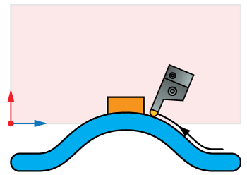
Retract in +X, -X, +Z, -Z: The retract movement is performed along the chosen axis.
|
|
Retract in +Z |
Retract in -Z |
|
|
Retract in +X |
Retract in -X |


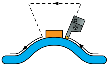
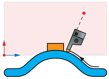
Retract in ZX plane: The retract movement is performed in the ZX-plane in the direction defined by the projection of the machined surface normal vector on the chosen plane.
Retract-optimized in ZX plane: The retract movement is performed in the chosen plane, similar to the Retract in ZX plane option; the differences are in the direction of the retract movements in the chosen plane. The contact points, at which collisions are detected, are projected on the chosen plane and connected into a contour. This contour is offset outwards by a distance equal to the sum of the tool radius and the Stock to leave values. This option enables you to perform the retract movements in optimal directions, generating the shortest tool path.
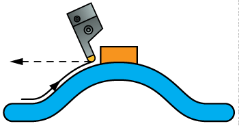
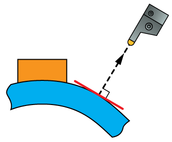
Retract along surface normal: The retract movement is performed in the direction of the drive surface normal at the contact point.
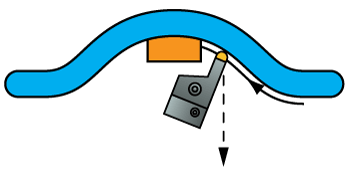
Retract along tool contact line: The retract movements are performed along the contact line between the tool and the machined surface.
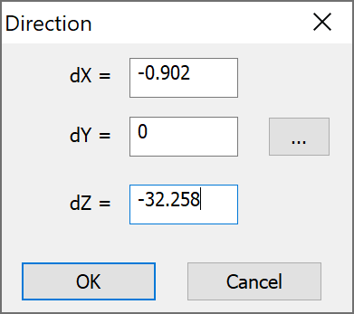
Retract in user-defined direction:
This option enables you to define the direction of the retract movements
by a vector. The Direction dialog
box (available with the Select
button) enables you to define the direction vector by its coordinates
(dX,
dY and
dZ parameters).
The ![]() button enables you to pick the start and end points of the vector directly
on the solid model.
button enables you to pick the start and end points of the vector directly
on the solid model.
This option enables you to move the tool path positions, in which possible gouging is detected, in the specified retract direction away from the check surfaces. The new tool path positions form the updated tool path free of gouges.
The tool path is generated until the position where the first gouge occurs. At this point the tool path calculation is stopped. The last cutting pass (where the gouge is detected) is not included into the operation tool path. You have to edit the machining parameters and calculate the tool path again to avoid the gouge.
SolidCAM checks only for collision between the tool and the check faces, without trying to avoid the collision; a warning message is displayed.
Using the simulation, you can check the collision areas and choose the appropriate method to avoid gouging.