Rough
The tool path movements are parallel to the Z-axis (longitudinal grooving) or to the X-axis (facial grooving). Semi-finishing and finishing passes are performed, if chosen by the user, at the end of the rough stage. The tool path calculation depends on whether CNC-machine cycles are used or not.

Use cycle = Yes
When the Use cycle option is set to Yes, the tool movements are performed according to the machine cycle of the particular CNC-controller.
Two cases are possible:
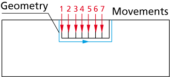
The geometry is composed of a single line parallel to the X- or Z-axis. If there is an offset, the tool starts at an offset from the start of the geometry and advances, according to the defined Step over, up to an offset from the end of the geometry; the offset is also taken into account in the depth to which the tool advances up to the geometry line. If semi-finishing or finishing is defined, the tool goes down on the perpendicular wall at the start of the geometry; then it retreats out and moves in Rapid mode to the end of the geometry and goes down on the perpendicular wall at the end of the geometry. Then it moves inside the material up to a distance equal to 1/3 of the tool width from the perpendicular wall at the start of the geometry.
The geometry is composed of several elements. The grooving is performed by tool movements perpendicular to the X-axis (Process type = Face) or to the Z-axis (Process type = Long). If the depth of the groove is too large, it can be divided into several steps by defining the value of the Step down value in the Rough tab.
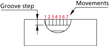
Steps in grooving
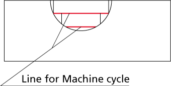
The program tries to generate the shortest GCode possible by generating a GCode groove cycle for any straight line longer than the tool width.
Use cycle = No
All the tool movements are the same as the previous option but instead of using CNC-machine cycles the generated GCode uses G0 and G1 moves.
Use cycle = Cut
This option is very similar to the option where the CNC-machine cycle is used (Use cycle = Yes). The groove is performed by tool movements perpendicular to the X-axis (Process type = Face) or to the Z-axis (Process type = Long). Each one of these tool movements is a CNC-machine cycle.
Working area
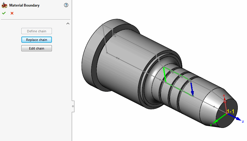
This option enables you to limit the tool path with a specified boundaries. When the working area is defined, SolidCAM calculates the whole tool path and then removes all tool path lines outside the working area.
Clicking the Working area button displays the Material boundary dialog box that enables you to define the geometry chain of the working area boundaries using the Chain Options dialog box.
When the Working area is defined, machining of the whole specified area is performed with working feed regardless of material found in this area.
When the Working area is not defined, the material is approached with rapid feed till the Safety distance level, and then machining is performed with working feed.

Related Topics