Semi-finish/Finish parameters
The Semi-finish/Finish tab enables you to define the parameters of the semi-finish and finish angled grooving.
|
Not all geometries are suitable for each type of Semi-Finish/Finish machining. Every method should be chosen deliberately. |
Semi-finish
A semi-finishing pass is a single pass that is executed before the finishing pass at an offset from the geometry.
|
No semi-finishing pass is performed. |
|
|
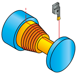
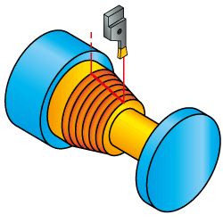
The semi-finishing pass is performed as follows: the tool moves in the direction of the geometry; continuous tool path is calculated along the geometry in the specified direction. The direction of machining is maintained throughout the tool path. |
 |
|
Semi-finishing of vertical segments of the geometry is performed in downward motions; therefore, the direction of machining can change from one segment to another. The connection between the tool path segments of different direction is performed through the Safety distance level. |
 |
| Clicking
the |
Semi-finish offset
This section enables you to define the offset from the geometry that will remain after the semi-finishing stage of the operation.
|
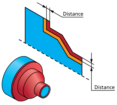
This option enables you to define the constant offset distance from the geometry. |
 |
|
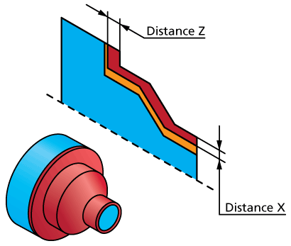
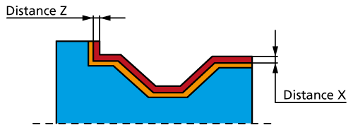
This option enables you to define different offsets from the geometry in the X- and Z-axis directions. The delta-X and delta-Z offsets from the geometry have to be defined. These two deltas define the vector that determines the direction of the offset. The Distance X parameter defines the offset in the X-axis direction. The Distance Z parameter defines the offset in the Z-axis direction. |
 |
|
This option is similar to the ZX option except that the program chooses the sign of the delta-X and delta-Z vector components in such way that the offset geometry does not intersect with the profile geometry. |
 |
Finish
A finishing pass is a single pass that is executed in the end of the operation.
|
No finishing pass is performed. |
|
|
The finishing pass is performed as follows: the tool moves in the direction of the geometry; continuous tool path is calculated along the geometry in the specified direction. The direction of machining is maintained throughout the tool path. |
 |
|
Finishing of vertical segments of the geometry is performed in downward motions; therefore, the direction of machining can change from one segment to another. The connection between the tool path segments of different direction is performed through the Safety distance level. |
 |
Finish on
SolidCAM recognizes the rest material areas left unmachined after the previous operations and enables you to perform finishing only in these areas or throughout the entire geometry.
|
The rest material is removed with the tool path based on the entire profile geometry. |
 |
|
Only the rest material areas are machined. |
 |
| You are prompted to specify the Start extension and End extension values to overlap the rest material area. | 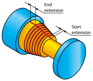 |
Compensation
This section is available only if the machine supports compensation and the tool origin is of Tangential type.
When this check box is not selected, the radius of the tool nose is not taken into account when calculating the tool movements. No tool nose radius compensation (G41/G42) is used in the GCode.
When this check box is selected, the radius of the tool nose is not taken into account when calculating the tool movements. However, the tool nose radius compensation (G41/G42) is used in the GCode.
Related Topics