Clearance area
The Clearance area is the area where the tool movements can be performed safely without contacting the material. The tool movements in the Clearance area are performed with the rapid feed.
Depending on the drive surface or your machining strategy, you can choose different clearance area types:
Automatic
This option is set as default. When this option is selected from the Type list, SolidCAM automatically determines the clearance area type, position and dimension to maintain the most suitable clearance level based on the part geometry and tool path type.
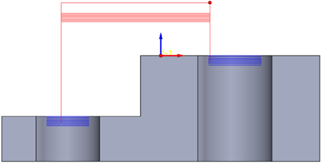
Plane
This option enables you to define the Clearance area by plane. The tool performs a retract movement to the Clearance area plane, and then a rapid movement in this plane.
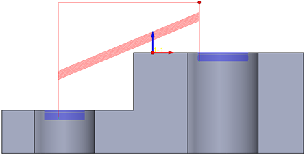
Direction- The Direction section determines the direction of the plane normal vector.
- The plane orientation is defined by a vector normal to the plane. With the X-Axis, Y-Axis and Z-Axis options, SolidCAM enables you to define this vector as one of the Coordinate System axis (X, Y or Z).
- The Automatic direction is similar to the machining direction and detects the plane height automatically.
The vector direction is defined by its coordinates (dX, dY and dZ parameters). Using the icons, you can pick the start and end points of the vector directly on the solid model, or select the entire face. |
|||
Height- The Height section provides you the options to determine the height of tool retraction.
|
|||
The Plane height parameter defines the distance between the appropriate Coordinate System plane and the Clearance area plane.
|
|||
The Incremental height parameter defines the distance to the Incremental clearance area plane for retract movements between two cuts. It is available only when the From/To incremental clearance area options are used for First entry and/or Last exit on the Approach/Retract tab of the Link page. Traversing type for incremental heightThe tool traverses the Incremental clearance area plane using one of the following methods:
|
|||
Cylinder
This option enables you to define the Clearance area as a cylindrical surface enclosing the Drive surface. The tool performs a retract movement to the Clearance cylinder, and then a rapid movement along the cylinder surface. Direction- The Direction section specifies the cylinder rotation axis direction and enables you to determine the clearance area orientation. The X-Axis, Y-Axis and Z-Axis options enable you to define the cylinder axes only parallel to one of the Coordinate System axes (X, Y or Z). With the Automatic option the rotation axis direction is automatically determined by the system. The User-defined direction option provides you with an additional capability to define the cylinder axis by an arbitrarily-oriented vector. It enables you to define the direction vector by its coordinates (dX, dY and dZ parameters). Using the icons, you can pick the start and end points of the vector directly on the solid model, or select the entire face. Radius- The Radius parameter enables you to specify the cylinder radius.
|
|
Through
|
|
Sphere
When this option is chosen, the Clearance area has a spherical shape; it should enclose your Drive surface geometry completely. The tool performs a retract movement to the Clearance sphere and then a rapid movement along the sphere surface. Radius- The Radius parameter enables you to specify the sphere radius.
Around
|