Surfaces and Curves Geometry
Drive surface definition
In the Drive surface section, choose the appropriate geometry from the
list or define a new one by clicking New
![]() . The Select
Faces dialog box is displayed. This dialog box enables you to select
one or several faces of the SOLIDWORKS
model. Click on the appropriate model faces. The selected faces are highlighted.
. The Select
Faces dialog box is displayed. This dialog box enables you to select
one or several faces of the SOLIDWORKS
model. Click on the appropriate model faces. The selected faces are highlighted.
To remove selection, click on the selected face again or right-click the face name in the list (the face is highlighted) and choose Unselect from the menu.
You can select faces using a color filter. In the Color section, click Define to choose a color from the Color pallette. You can also choose a color that has already been used in a surface. Click Pick from Model and choose the desired surface directly on the solid model. The chosen color is shown in RGB (Red, Green, Blue) color model. Click Find Faces. SolidCAM selects all faces having the chosen color.
When transferring model files from one CAD system to another, the direction of some of the surface normals might be reversed. For this reason, SolidCAM provides you with the capability to display and edit the normals of model surfaces during the geometry selection.
The Show direction for highlighted faces only check box enables you to display the surface normals for the specific highlighted faces in the list. The Show direction for selected faces check box enables you to display the normals direction for all the faces in the list. |
 |
SolidCAM enables you to machine surfaces from the positive direction of the surface normal. Sometimes surfaces are not oriented correctly and you have to reverse their normal vectors. The Reverse/Reverse All command enables you to reverse the direction of the surface normal vectors.
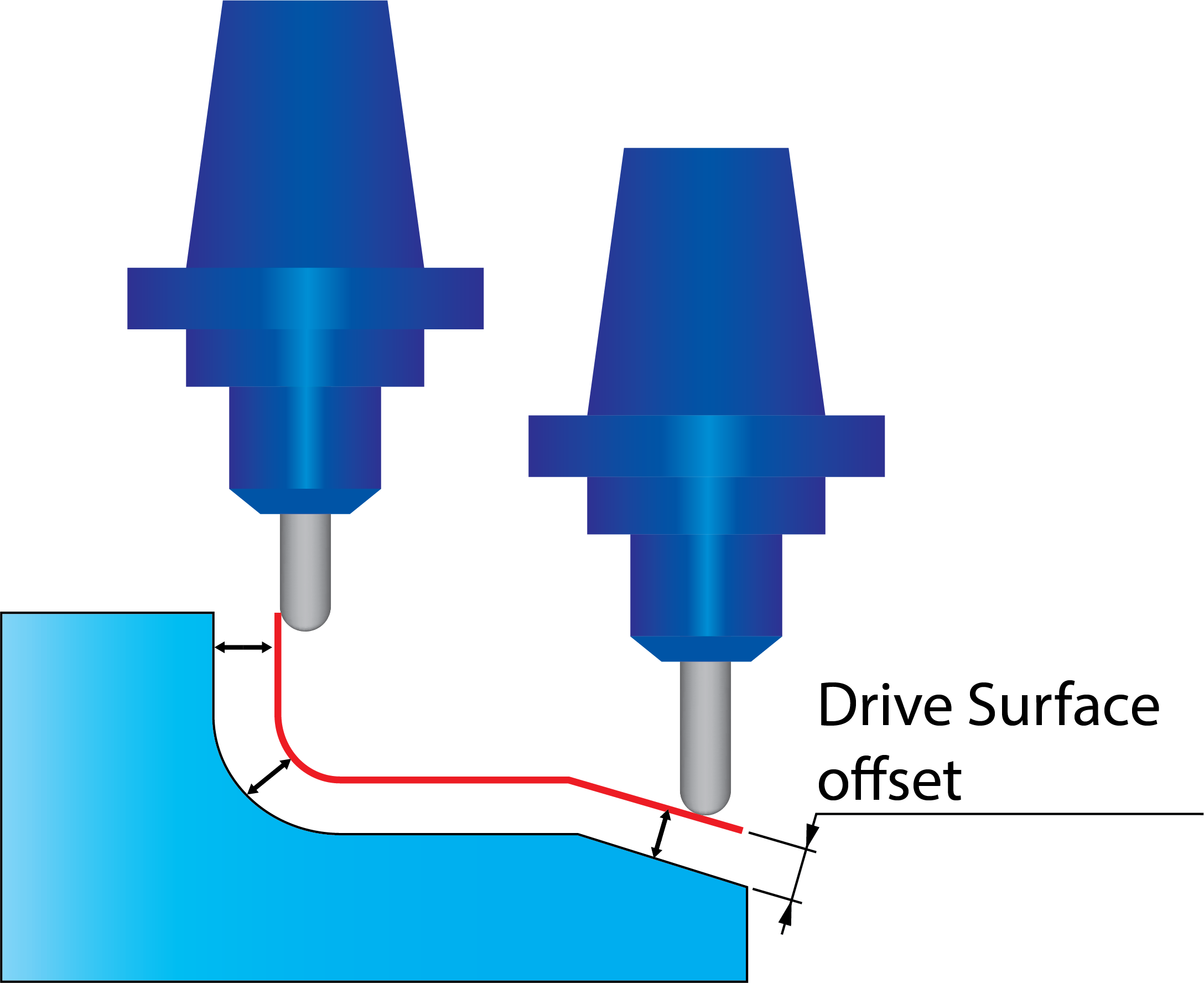
Drive surface offset
The Drive surface offset parameter enables you to define a machining allowance for the drive surface. The machining is performed at the specified distance from the drive surface. |
 |
|
The offset is three-dimensional and expands the faces in every direction. |
Some Sim. 5-Axis machining strategies use additional curve geometries for the tool path generation. SolidCAM enables you to define such geometries using the Geometry Edit dialog box.
Work type
This section is available only for Parallel cuts strategy. It offers you two ways in which the tool path cuts can be performed:
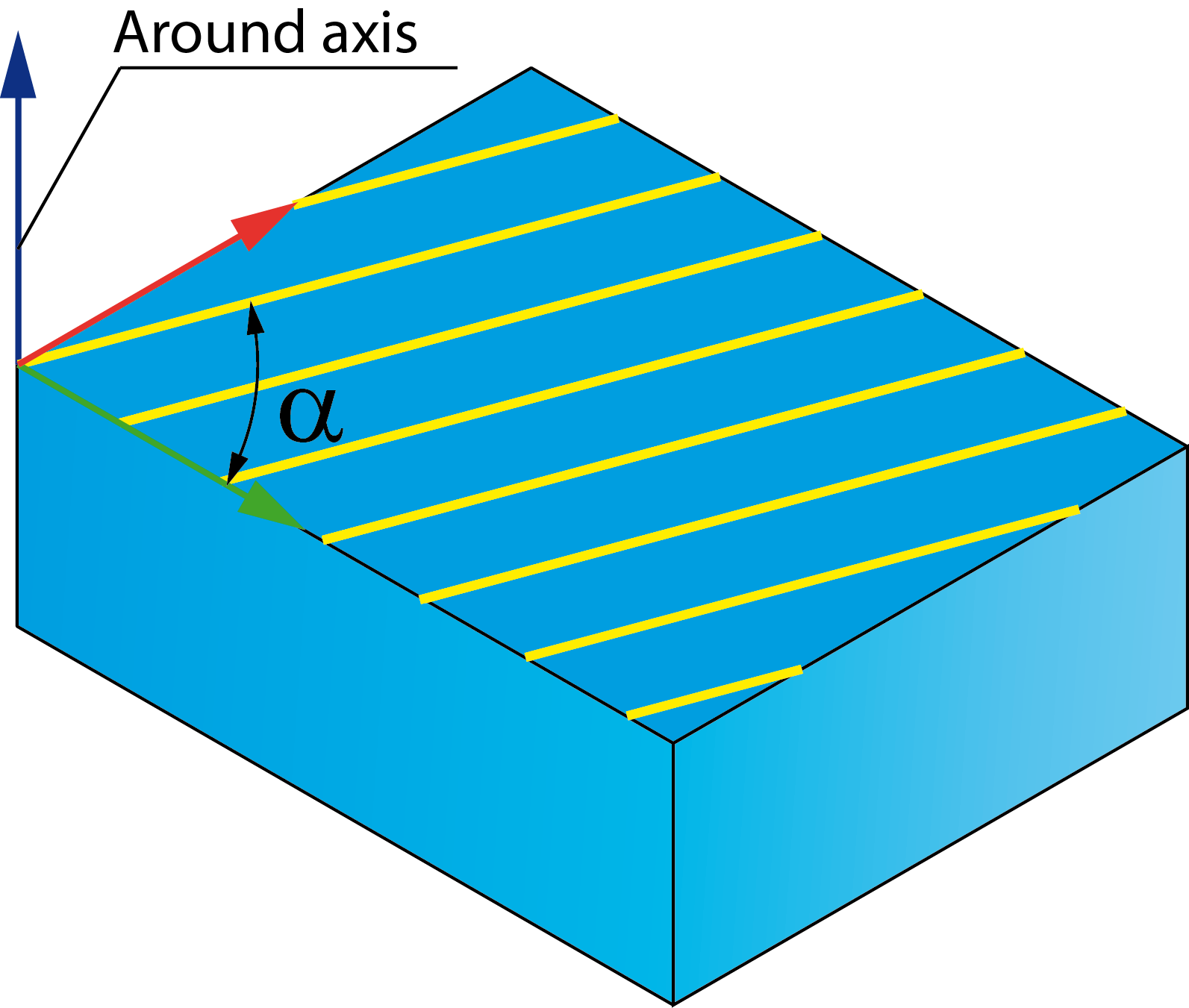
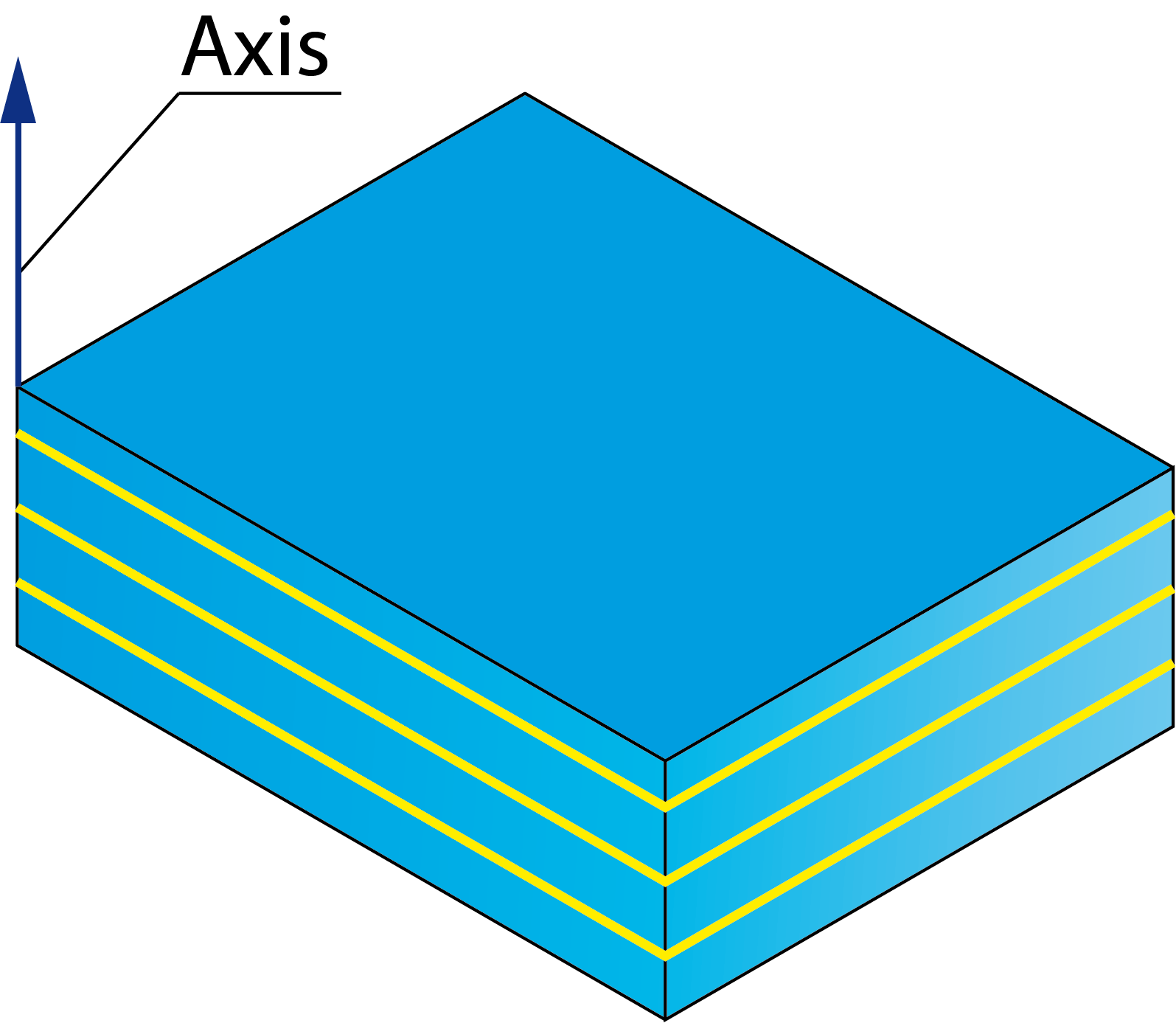
The Around axis list enables you to choose the axis (X, Y or Z) around which the tool path cuts will be generated.
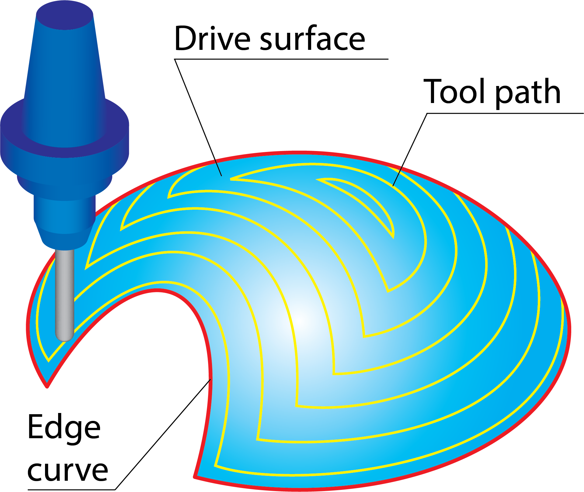
Edge curve
This section is available only for the Parallel to curves strategy.
The Edge curve section enables you to define lead curve for the operation using the Geometry Edit dialog box.
|
 |
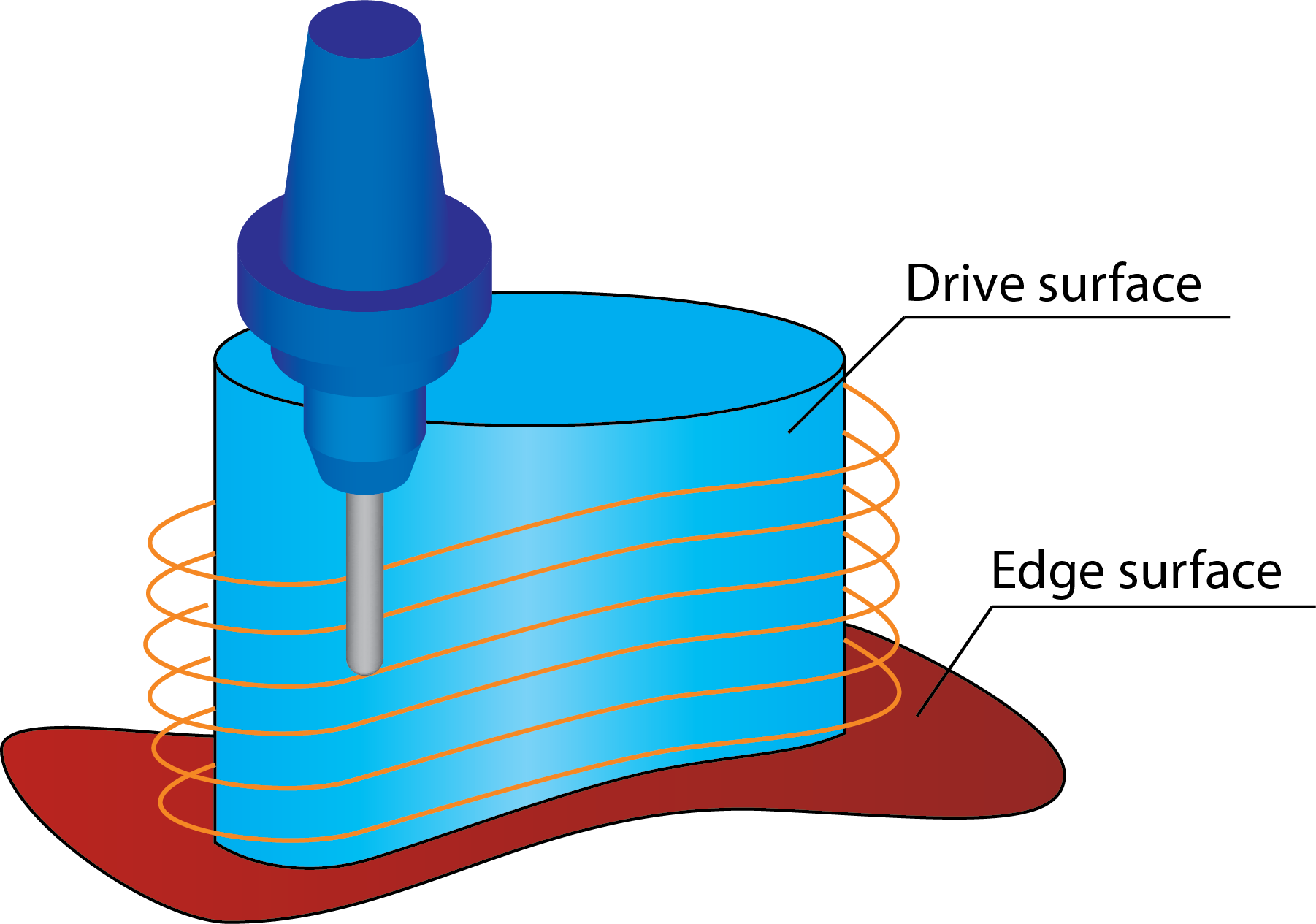
Edge surface
This section is available only for Parallel to surface strategy. It enables you to generate the tool path on the Drive surface parallel to the specified check surface.
The Edge surface section enables you to define the check surfaces geometry for the tool path generation.
|
 |
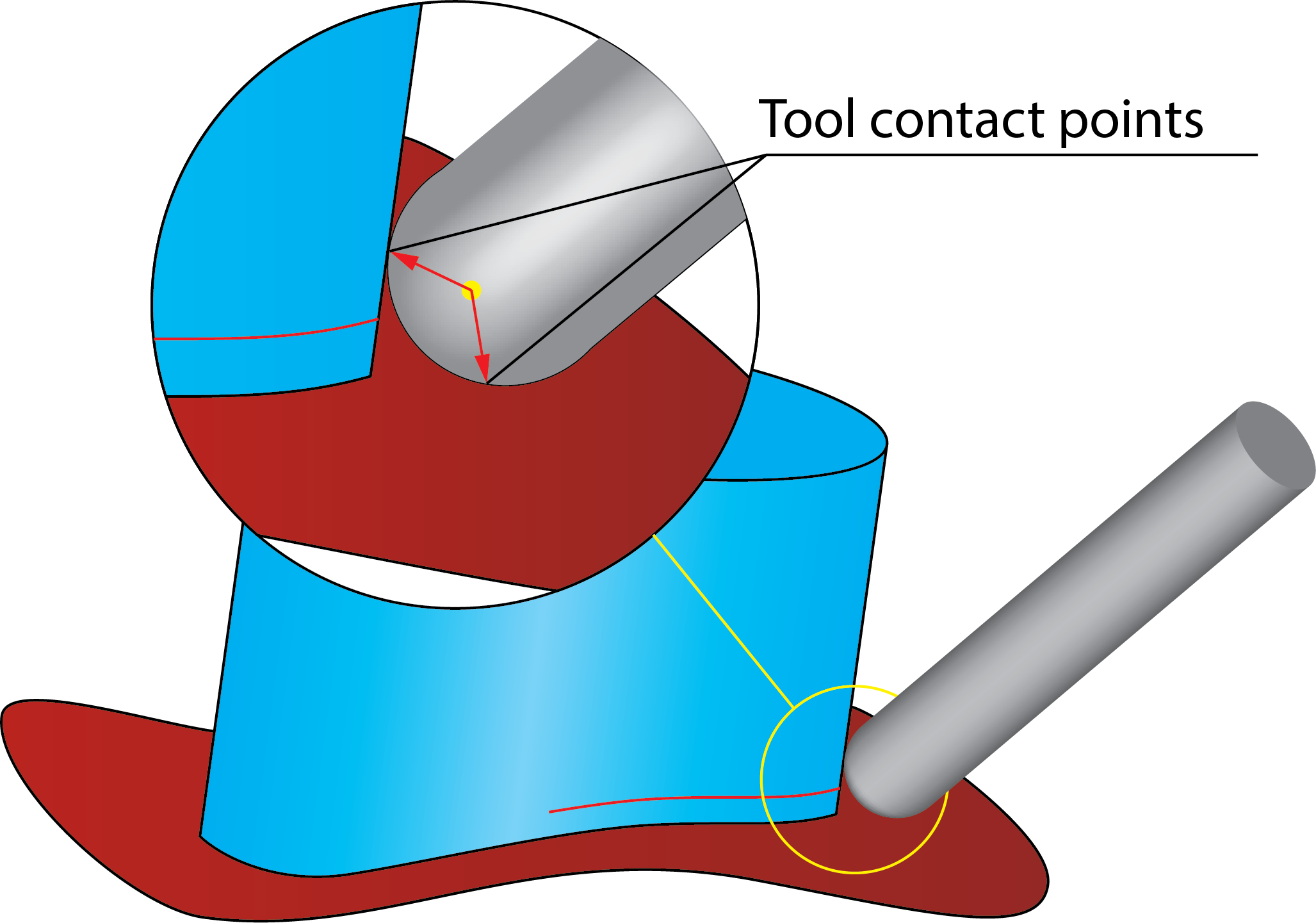
||
When a ball-nosed tool is used with this strategy, it is recommended to use the Tool center based calculation option. With this option, the passes close to the check surface will be generated in such way that the tool is tangent to both the drive surface and the check surface. If the calculation is not based on the tool center, a wrong tool path is generated. |
 |
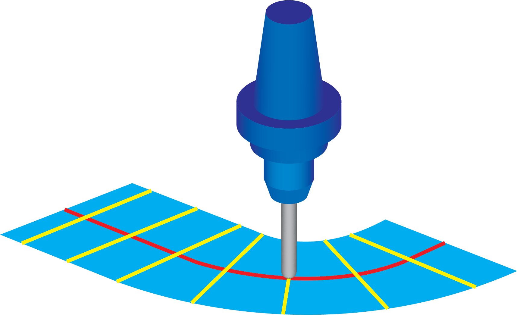
Lead curve
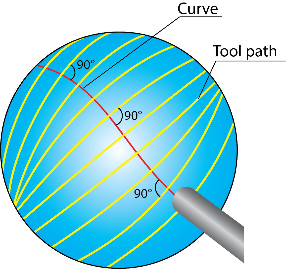
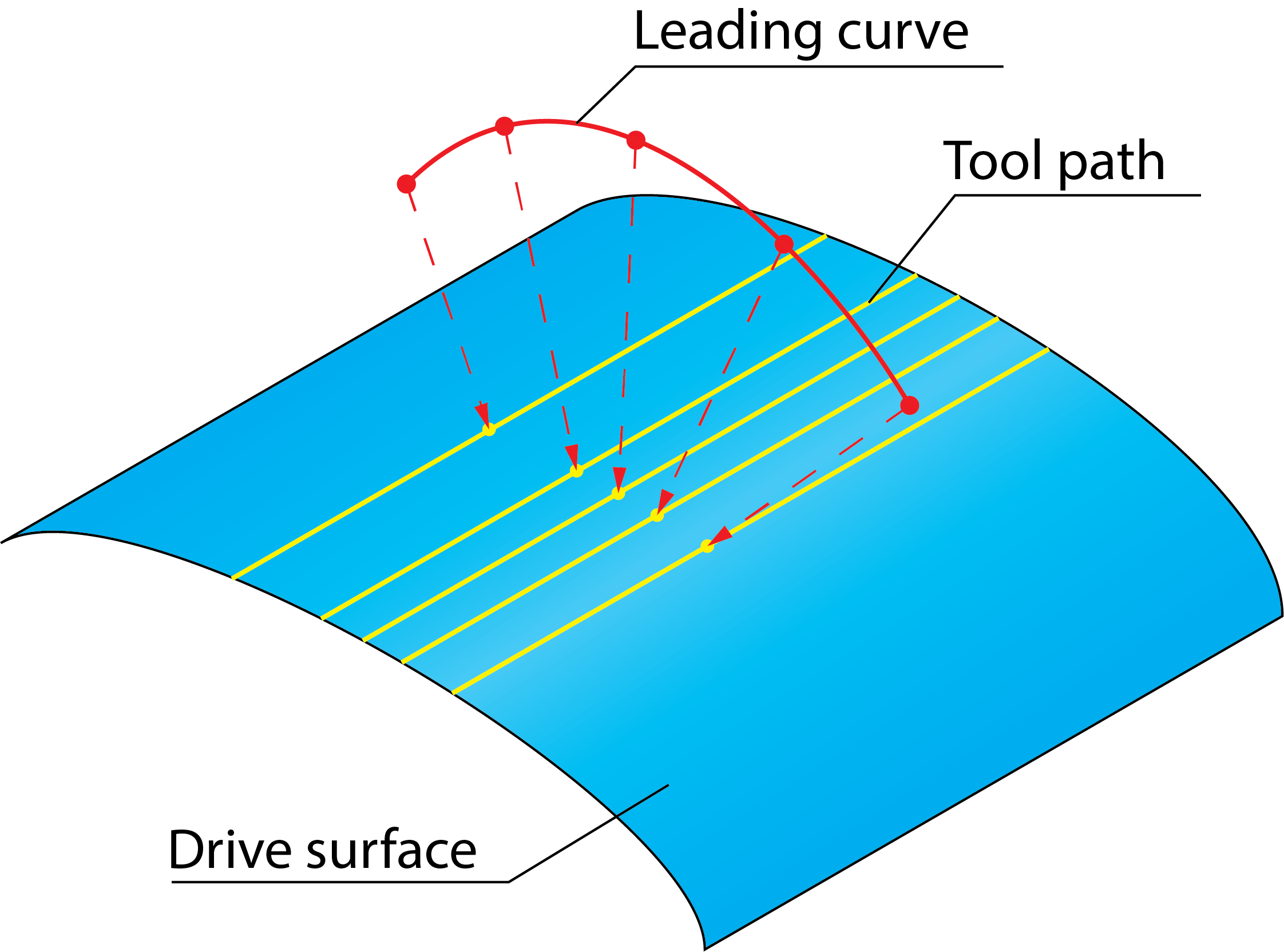
This section is available only for Perpendicular to curve technology, which enables you to generate the tool path orthogonal to the Lead curve defined in the Geometry section.
|
 |
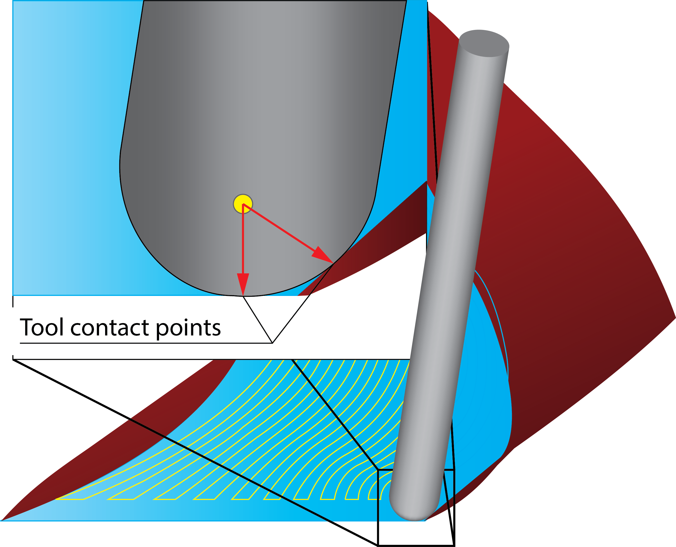
The lead curve geometry does not have to be located on the surface. During the tool path calculation, SolidCAM generates in each point of the lead curve virtual points on the curve. The distance between these points is determined by the Step over value. SolidCAM projects these points onto the drive surface; the direction of the projection is the normal vector of the curve at the virtual point. Where the normal vector intersects with the surface, a virtual surface point is generated. The passes are generated through these points, normal to the lead curve.
|
 |
|
If the cuts cross each other at the edge of the surface, caused by a inappropriate lead curve, you will not get an acceptable result. The lead curve must be located exactly on or above the drive surface. If the curve is not located above the surface, no tool path is generated. When only a part of the lead curve is located above the surface, only where the normal vector of the lead curve intersects with the drive surface a tool path is generated.
|
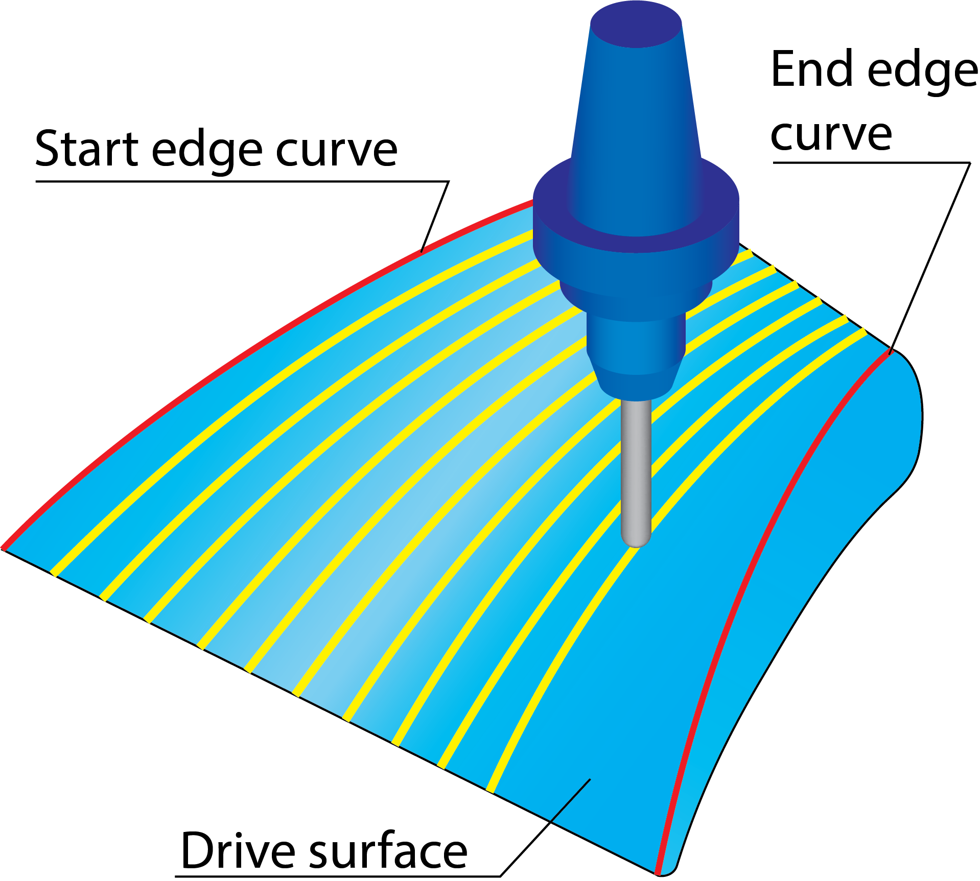
Start and End edge curve
The Morph between two boundary curves creates a morphed tool path between two leading curves. The generated tool path is evenly spread over the drive surface.
The Start edge curve and End edge curve sections enable you to define the leading curves for the morphing using the Geometry Edit dialog box.
|
 |
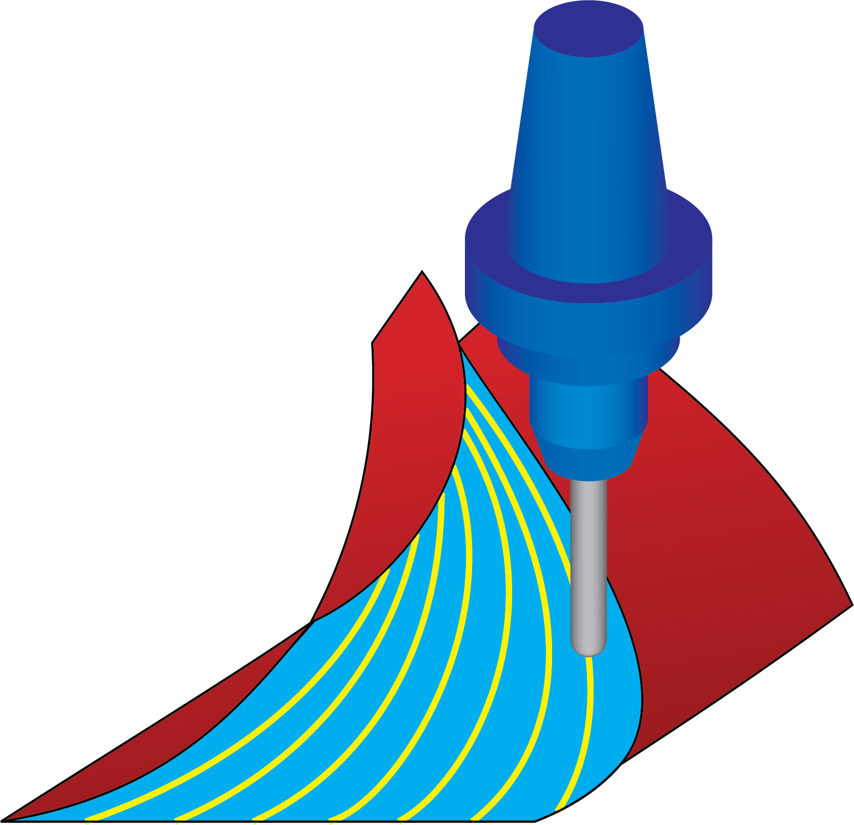
Start and End edge surface
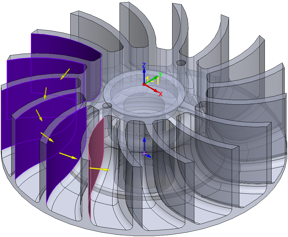
The Morph between two adjacent surfaces technology enables you to generate the morphed tool path on a drive surface enclosed by two check surfaces. The tool path is generated between the check surfaces and evenly spaced over the Drive surface. This strategy can be used for the machining of impellers with twisted blades. The Start edge surfaces and End edge surfaces sections enable you to define the check surfaces geometry for the tool path generation.
|
 |
||
When a ball-nosed tool is used with this strategy, it is recommended to use the Tool center based calculation option. With this option, the passes close to the check surfaces are generated in such way that the tool is tangent to both the drive surface and the check surface. If the calculation is not based on the tool center, a wrong tool path is generated. |
 |
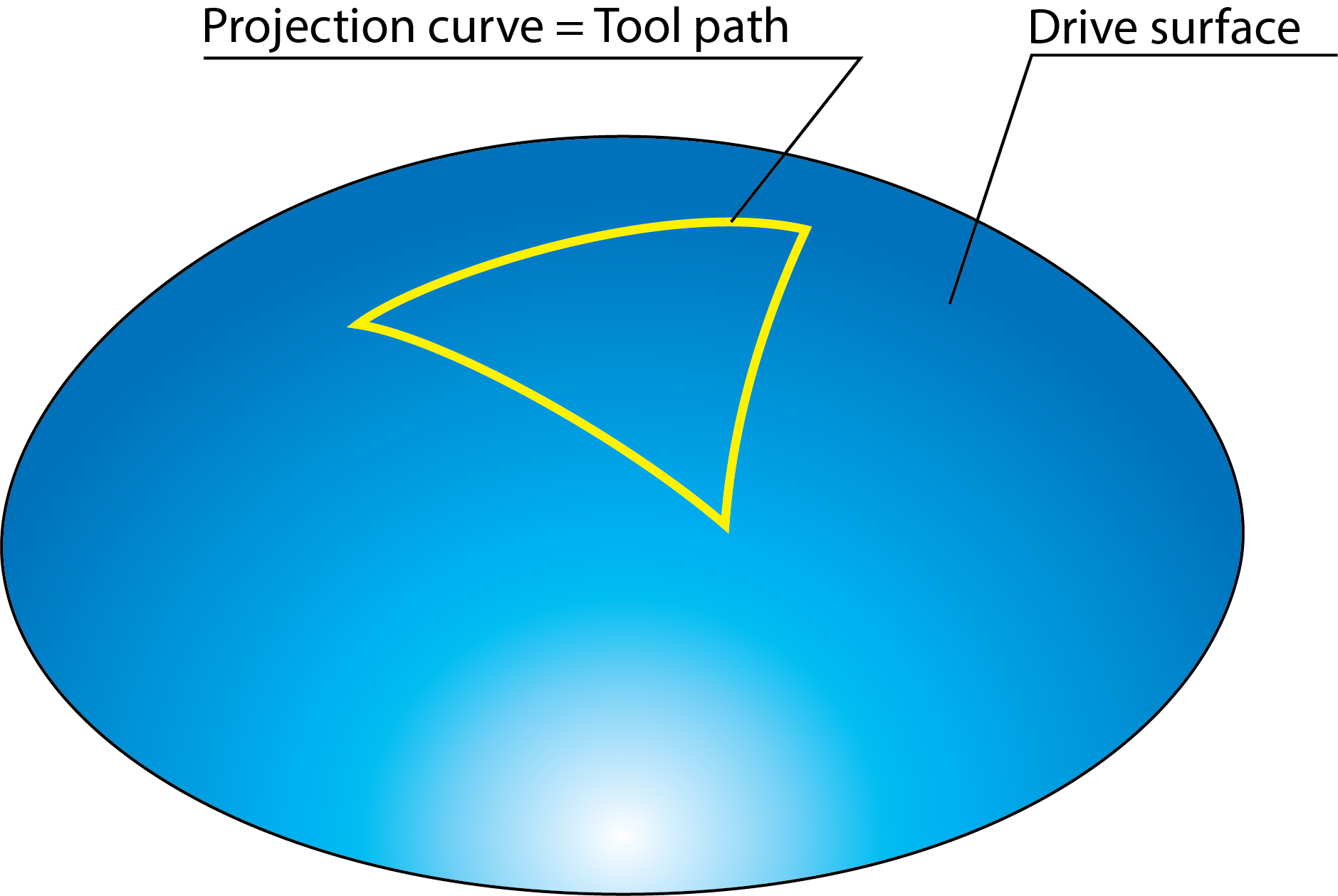
Projection curves
This section is available only for the Projection technology that enables you to generate a single tool path along a curve. The Projection curves section enables you to define the curves for the tool path generation.
|
 |
Max. projection distance
When the User defined strategy is chosen in the Projection technology, the system expects to get projection curves lying on the drive surfaces.
Due to tolerance issues in CAD systems, sometimes the curves do not lie exactly on the drive surfaces. This error can be compensated by the Maximal projection distance value. For example, if the value is 0.1 mm, it allows to have the projection curve 0.1 mm away from the drive surfaces.
Direction
This section enables you to specify the direction to which the curves are projected.
X, Y, Z- The curve direction is defined as parallel to one of the Coordinate system axes.
Line- The projection vector is defined by a line that you can pick directly on the solid model.
Surface normal- This option projects the curve into the normal direction of the surface below.
If the curve/pattern lies exactly on the face, the tool path has same shape and position as the curve.
If the curve/pattern lies above the drive surfaces, the tool path changes. The tool path is built only on an interval between those normals that intersect the curve.
The projection has to lie within the Max. projection distance to the drive surface, otherwise the curves cannot be considered for projecting.
Center point
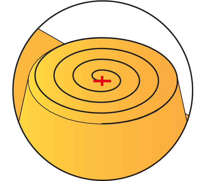
For Spiral/Radial strategies, SolidCAM creates a spiral/circular pattern, which is then projected on the drive surface. The parameters of the virtual circle are defined in the Geometry section.
The Center point section enables you to define the position
of a circle center point. It can be defined manually by entering
the coordinate values in XYZ field, picking the point directly
on the solid model using the |
 |
|
 |
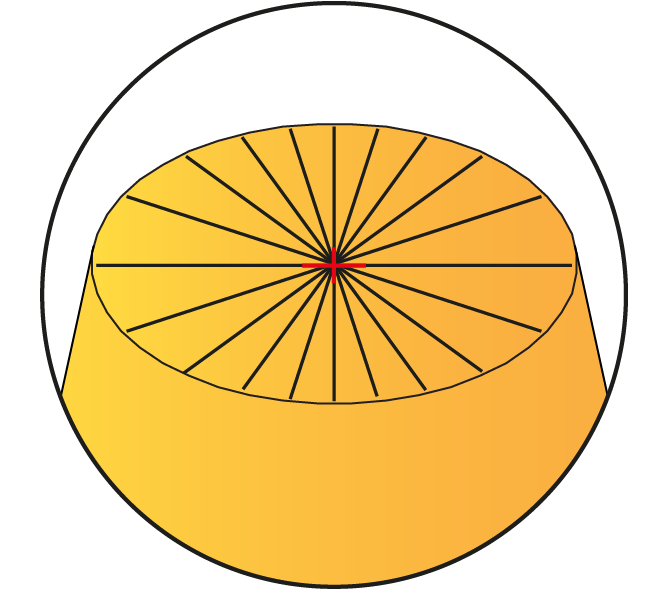
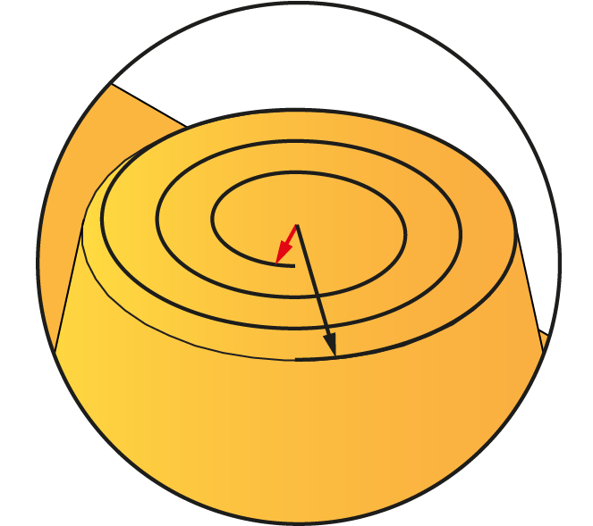
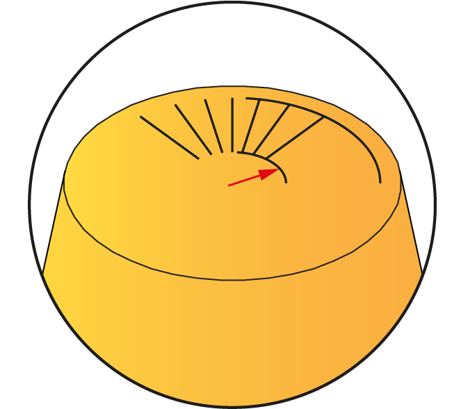
Radius
The radial pattern is defined by inner and outer circles projected on the drive surface.
Start- This option enables you to create a virtual inner circle that starts the tool path from this inner circle so that the tool does not rub at the converging point where the radius is zero. |
|
|
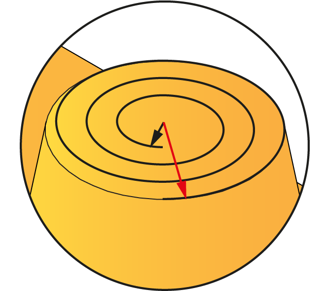
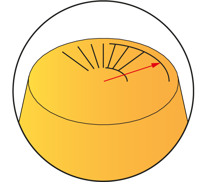
End-This option enables you to stop the tool path at the extreme end of the virtual outer circle. |
Spiral |
Radial |
The Auto detect option enables you to detect the required maximum radius to machine the surface automatically.
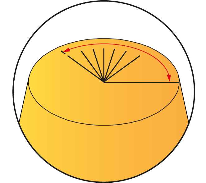
Angle
This option defines an area based on two angles for the tool path calculation.
Start- This parameters defines the starting angle of area definition for the tool path calculation. |
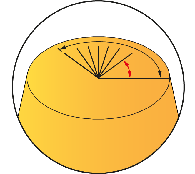 |
End- This parameter defines the ending angle of area definition for the tool path calculation. |
 |
|
The option of Angle is available only in the Projection (Radial) technology.
|
Offset
This section enables you define the rule for creating offsets from the Projection curves.
Direction
This option enables you to set where the offsets are created: on the Left/Inside, Right/Outside, or Both sides of the projection curve.
Number of left cuts
This value defines how many cuts are machined on the left side of the projection curves.
Number of right cuts
This value defines how many cuts are machined on the right side of the projection curves.