Levels
This page enables you to define the machining levels for the Multiaxis Drilling operation.
Clearance Area
The Clearance area is the area where the tool movements can be performed safely without contact with the material. The tool movements in the Clearance area are performed with rapid feed.
Depending on the part shape, you can choose different clearance area types:
Automatic
| When this option is selected, clearance area direction, type and value are automatically set by SolidCAM based on the part geometry and tool path type |
Plane
This option enables you to define the Clearance area by plane. The tool performs a retract movement to the Clearance plane and then a rapid movement in this plane. |
SolidCAM enables you to define the location and the orientation of the Clearance plane.
Cylinder
This option enables you to define the Clearance area as a cylindrical surface. The tool performs a retract movement to the Clearance cylinder, and then performs a rapid movement along the cylinder surface. |
SolidCAM enables you to define the location, orientation and radius of the Clearance cylinder.
Sphere
When this option is chosen, the Clearance area has a spherical shape. The tool performs a retract movement to the Clearance sphere and then a rapid movement along the sphere surface. |
SolidCAM enables you to define the location and radius of the Clearance sphere.
Distances
This section enables you to define the Retract and Entry safety distance for the tool to approach and retract from the part.
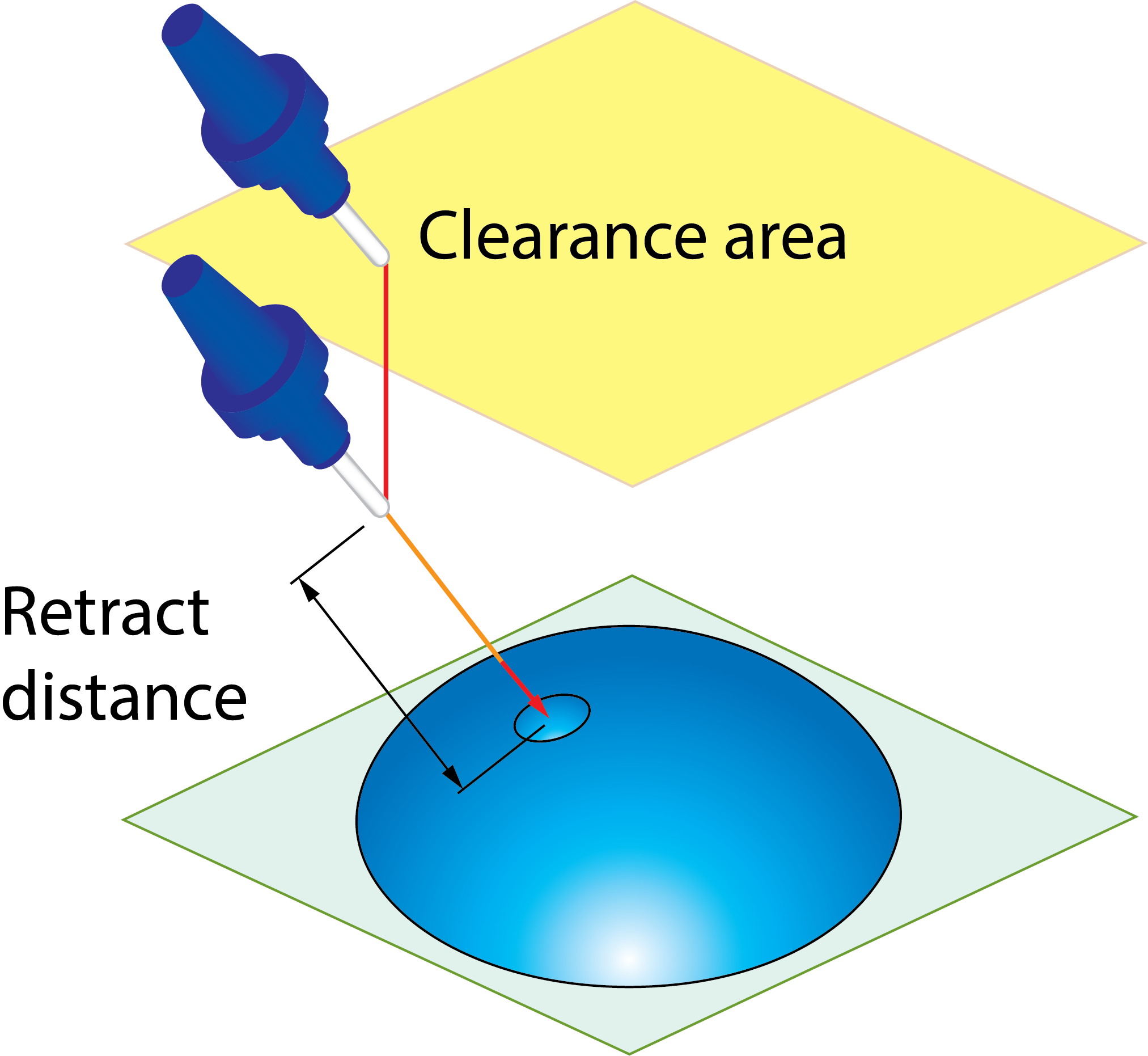
Retract distance
In the Clearance area, the tool rotates to the final orientation for the first cut. After the rotation, the tool performs a rapid descent movement to the level specified by the Retract distance parameter. The Retract distance is measured from the start position of the drill. |
 |
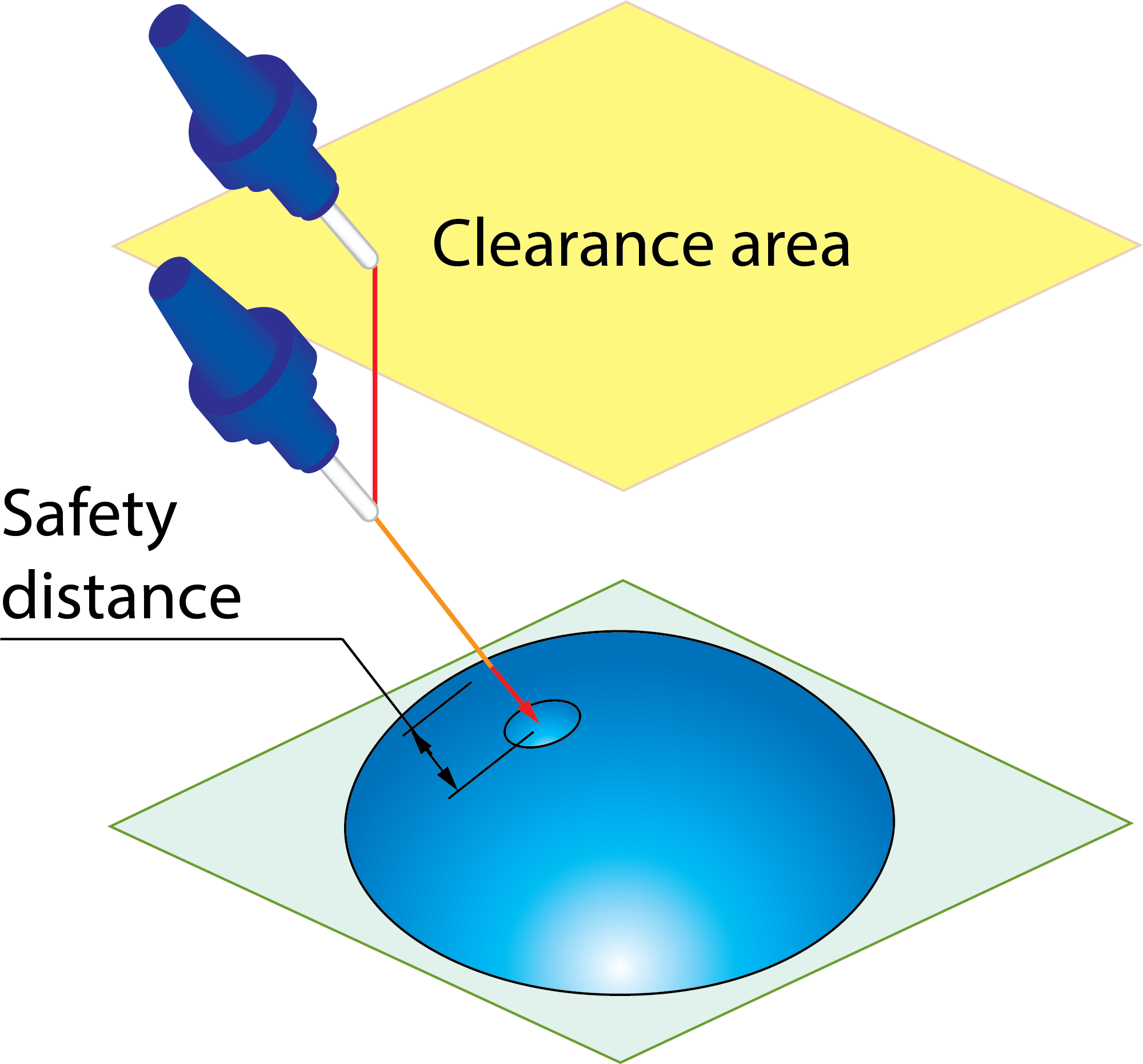
Safety distance
After the descent movement to the Retract distance level, the tool starts the approach movement to the material. The approach movement consists of two segments. The first segment is performed with rapid feed up to the Entry safety distance. From the Entry safety distance level, the approach movement is performed with the cutting feed. |
 |
Depth edit
This button displays the Depth Edit dialog box that enables you to choose the drills to be included in the geometry and modify the geometrical parameters of the chosen drills.
Holes Tree
This section displays the list of all drills chosen for the geometry. All the drills in the list are structured in Groups. Each Group has the same Delta start, Drill depth, Delta depth and Depth type data displayed in parentheses.
When one of the items of the list is selected, the relevant parameters are displayed in the Delta start, Drill depth, Delta depth and Depth type sections. The corresponding drills are highlighted on the solid model with the arrow indicating the machining direction.
The right-click menu is available on each item in the list.
Restore Data from Model
This command enables you to restore the default parameters recognized on the Target model for the selected item (a group or a single drill). When this command is applied, SolidCAM checks the Holes Tree items and reorganizes them into groups according to the changed parameters.
Restore Data from Model to All
This command enables you to restore the default parameters for all the drills in the list. When this command is applied, SolidCAM checks the Holes Tree items and reorganizes them into groups according to the changed parameters.
Select All/Unselect All
These commands enable you to toggle the selection of all recognized drills.
Hole Diameter (D)
This section enables you to set the diameter value and apply it to selected drills.
Delta start (ds)
This section enables you to change the Z-value of the default drilling start point recognized on the Target model. When a positive value is entered, the start point is moved upwards from the default position. When a negative value is entered, the start point is moved downwards from the default position.
Drill Depth (d)
This section enables you to define the value of the drilling depth and apply it to selected drills.
Delta Depth (dd)
This section enables you to set the offset for the cutting depth and apply it to selected drills.
Depth Type
This section enables you to define the Depth Type for selected drills. You can define the diameter on the conical part of the drilling tool that will reach the specified drilling depth during the machining. You can also deepen a drilled hole in order to obtain a given diameter at the specified drill depth.
The following Depth Type options are available:
Cutter tip(ct)- The tool tip reaches the defined drilling depth.
Full diameter(fd)- The tool reaches the defined drilling depth with the full diameter.
Diameter value(dv)- The tool reaches the defined depth with the drill cone diameter specified by the Diameter value parameter.
The Apply button, in each of the sections described above, enables you to apply the defined parameter to the selected list item (a group or a drill).
The All check box enables you to apply the updated values to all the items in the list.
Advanced parameters
Arc fit
This option provides tangential arcs for the approaching and retracting link segments. You can specify the radius of the arc. This option can be applied to Clearance area, Retract distance, and Safety distance.
Arc radius
This option fits an arc to sharp angles in the checked areas and distances.
Interpolation Tilt angles
This section enables you to control the interpolation of link movements in the Clearance area.
|
The Advanced tab is available only when the Advanced check box is selected. |