Tool axis control
This page enables you to control the tool axis orientation during the SWARF machining.
Output format
5 Axis -By default SWARF machining creates a 5-Axis output to be able to machine every arbitrary formed surface.
3 Axis- Selecting 3 Axis from the Output format list enables you to machine a surface using just one cut. When this option is selected, only the SWARF surfaces and Floor surfaces options are available for selection in the Part definition section of Geometry page.
4 Axis- The output can be limited to 4-Axis to be swarfing to 4-Axis machines. This option is useful as the tool orientation is aligned for a complete 4-Axis cycle.
Selecting 4 Axis from the Output format list enables the sections of Rotary axis, Tilt angle, Locked at angle and Flip.
Rotary axis
Click Rotary axis to display the 4th Axis dialog box. This dialog box enables you to choose the rotary axis (X-, Y-, Z-axis of the Coordinate System or another User-defined axis).
When Point tool to rotary axis check box is selected, the tool always points to the user defined rotary axis.
Tilt angle reference
You can select the tilt angle to be Orthogonal to rotation axis or Parallel to rotation axis.
Locked at angle
The Locked at angle parameter enables you to specify the angle at which the axis is locked.
Flip
When the Flip check box is selected, it mirrors the tilt angle to the other side of the tool axis.
General
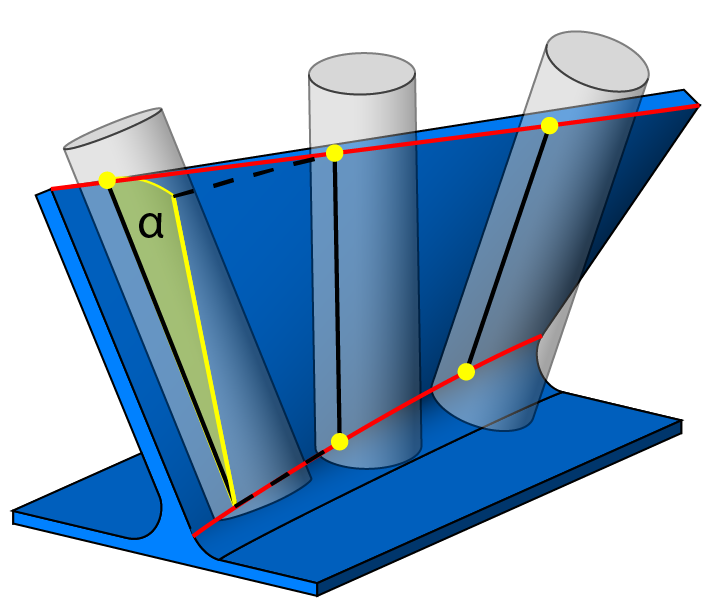
Maximum angle stepThe Maximum angle step parameter enables you to define the maximum allowed angle change between two consecutive tool path points. |
 |
||
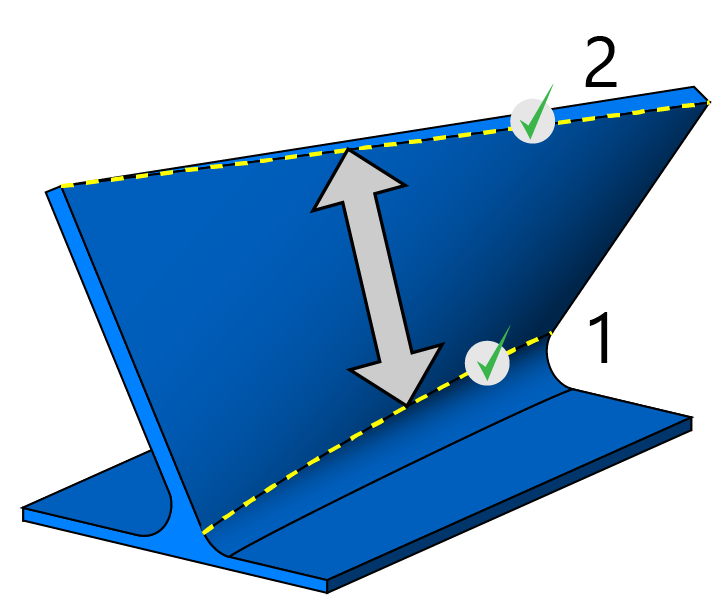
Swap curvesThis option allows you to exchange the upper and lower curves for defined Swarf surfaces.
|
 |
||
|
|
|||
Minimize rotation axis changesIn a situation when the tool is located in the center of the machine, the machine rotary axis can rotate very fast, and singularity occurs. This option enables you to minimize the axis changes, providing smooth tilting of the tool along the surface.
|
Fanning
Fanning distanceIf the upper and lower curves have different length, the tool cannot cut with the flute full length, therefore only the tool tip moves. This movement is called fannining. To avoid the tool stoping at the shorter curve, you can set a fanning distance. When the tool arrives to the point located at the specified distance from the end of the curve, it starts to tilt and moves further with the flute full length.
|