Rotate&Translate
The Rotating strategy is useful for parts with multiple identical elements arranged in a circular pattern. Instead of adding a separate operation and defining the same parameters for each of these patterns, you can have the same tool path repeated a given number of times by rotation around a specific axis.
The Rotate/Translate Tool Path dialog box enables you to define the parameters of rotation.
Orientation
Rotary axis around
This option provides you the choice of the axis around which your tool path will be rotated. You may choose between the X-, Y- or Z-axis of the current Coordinate System or define a rotary axis vector by an end point (the start point is automatically considered to be in the Coordinate System origin).
Rotary axis base point
This option enables you to define the position of the rotation axis. When you click the Select point button, the Select point dialog box is displayed with the coordinates of the point you pick on the model.
Number of steps
This parameter enables you to define the number of instances of the circular pattern. In other words, it defines how many times the initial tool path will be repeated around the rotation axis.
Rotate
Start angle
This parameter enables you to define the rotation angle for the first tool path instance of the circular pattern.
Rotation angle
This parameter enables you to define the angle between two adjacent instances of the circular pattern.
Translate
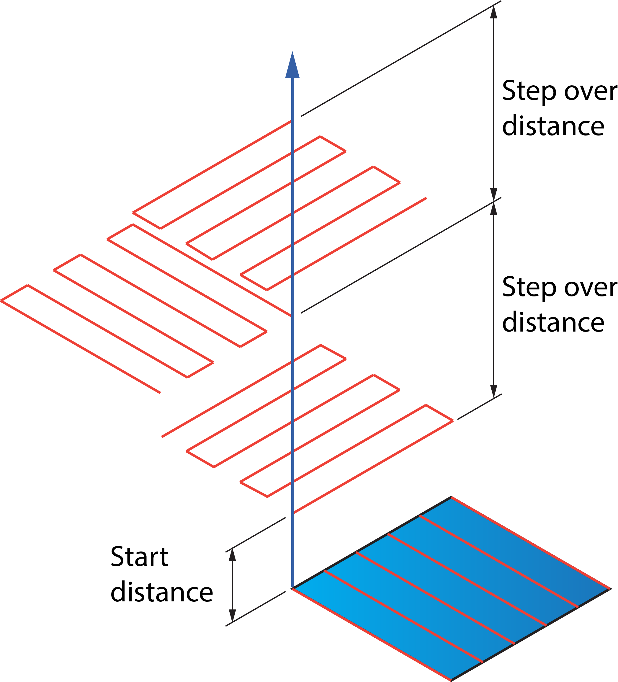
This section contains two parameters that enable you to transform a 5-axis tool path:
These distances are measured along the transformation axis defined in the Rotary axis around list.
Sorting
Sort by
This option enables you to choose whether the whole tool path will be rotated or only a certain part of it. The following options are available:
- Complete tool path- With this option the whole tool path will be rotated.
- Passes- With this option the whole tool path will be rotated. The resulting tool path will be sorted and linked by passes.
- Slices- With this option the whole tool path will be rotated. The resulting tool path will be sorted and linked by slices.
- Partial tool path- With this option the portion of tool path specified by a percentage is rotated. The percentage is specified by the Percent of whole tool path parameter.
Apply linking
This option enables you to link the tool path either before or after the rotation.
- Before rotation- With this option,SolidCAM generates the initial tool path, links it and then performs the rotation. In this case the link movements in all the rotated instances of the tool path are the same.
- After rotation- With this option, SolidCAM applies linking after the tool path rotation. It is recommended to use this option with the collision control activated to avoid possible collisions in the link movements.

The Sorting section of the Sim. 5-Axis Rotate/Translate Tool Path dialog box is not applicable in SWARF Machining and Geodesic Machining.
