Roughing and More
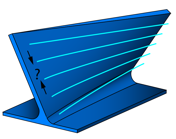
Pattern slices
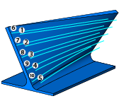
This section enables you to perform the machining in a single slice or in multiple slices. The machining area should be cut with multiple step depths in case the tool flute has short length. When the number of slices it set to 1, a single slice will be generated at the bottom curve.
|
Make sure that the flute length is sufficient for this cut. |
Depth steps
This option enables you to define multiple cuts along the tool axis direction.
This option enables you to define the Distance between two consecutive slices. |
 |
This option enables you define the Number of slices between two curves. |
 |
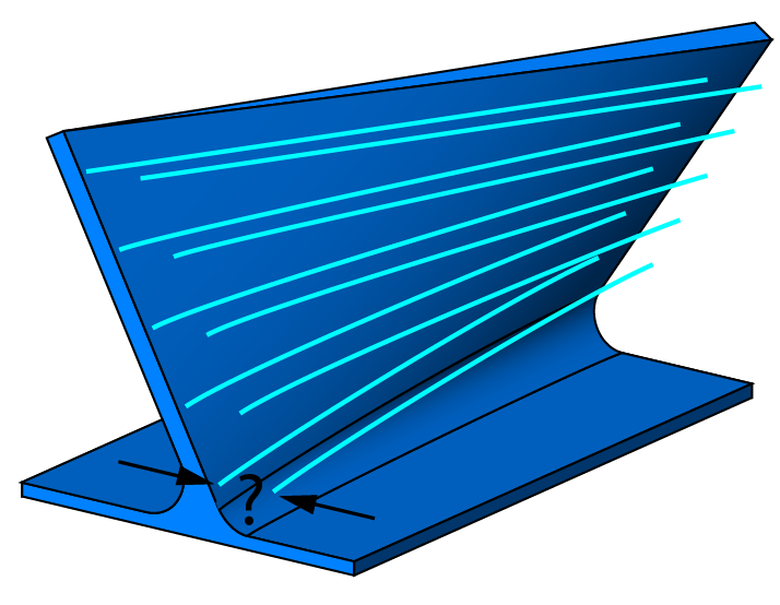
Pattern
This parameter enables you to create the tool path pattern using the options of Morph, Step from top, and Step from bottom.
|
In this option the tool path is created as a morph between the upper and bottom edge. |
 |
|
In this option the tool path pattern is parallel to the upper edge |
 |
|
In this option the tool path pattern is parallel to the bottom edge. |
 |
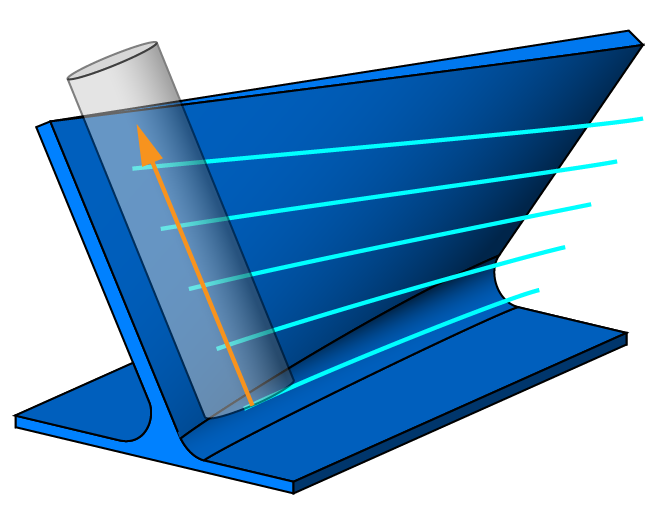
Direction
The multiple slices are copies of the initial slice. Their direction can be defined along the tool axis, along the contact line or by following the surface topology. In cases where a conical tool is used, the retraction along the tool axis is not applicable. The tool would leave the surface in the upper cuts due to the conical angle.
|
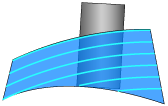
This option enables the tool retraction into tool axis direction or tool contact line while performing the depth steps. The multiple slices are equidistant between the upper and the bottom curves. |
 |
|
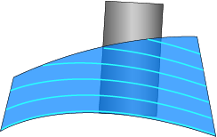
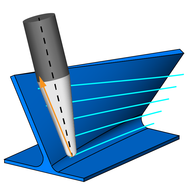
This option enables you to set the conical tool in contact with the actual swarf surface. The material is machined only downwards. |
 |
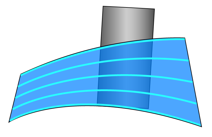
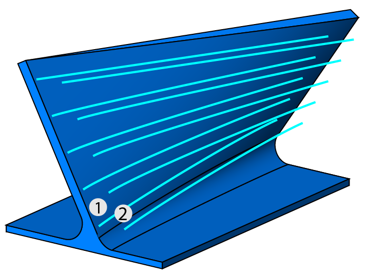
This option enables you to create multiple slices that follow the actual curvature of the swarf surfaces. Following the surface topology can be beneficial in the machining of convex shapes such as gear flanks or pressure sides from impeller blades.
|
|
|
The Direction list is available when By slice distance is selected for Depth steps or |
Tool guidance
This section enables you to guide the tool damping and tool shift motions.
Tool dampening
The Tool dampening list provides you the options of None and User-defined. Using the option of User-defined, you can make the tool path smoother and avoid vertical jumps by the dampening distance set in the Direction field.
Tool shift
The following options determine how the tool is shifted for each slice:
Pattern layers
This section enables you to define multiple layers in the direction of the material.
|
This field enables you to define the number of multiple offset layers from the slices. |
 |
|
This field enables you to define the layer distance along the direction of tool axis. |
 |
|
The Layer distance option is available only when the Number of layers is more than 1. |
Sorting
This section enables you to define the linking method of the passes for machining.
Sequence
This option enables you to link the tool path by the layers or by slices.
|
When this option is chosen, all the roughing and finishing offsets of the current cutting pass are performed before moving to the next cutting pass. |
 |
|
When this option is chosen, all the cutting passes of the current offset level are performed before moving to the next offset level. |
 |
Rotate&Translate
The Rotate&Translate button displays the Rotate / Translate Tool Path dialog box.
|
The Sorting section of the Sim. 5-Axis Rotate/Translate Tool Path dialog box is not applicable in SWARF Machining. |
Mirror
The Mirror option enables you to create a mirror image of the tool path by reflecting it symmetrically around any selected axis and base point.
More
Links between passes
The Links between passes option enables you to define how the tool moves between consecutive cutting levels. In SWARF machining, this option is enabled when the Number of layers value is greater than 1.