Tilted relative to impeller machining layer
This tilting strategy is used for machining of impeller blades. Generally, the tool axis in this strategy is normal to the floor face of the impeller. The lag and side tilting can be adjusted by defining the corresponding parameters in the Angles section. Such general tool tilting definition might cause gouges in certain types of impellers, especially in those with splitter blades, therefore additional local tilting definition might be required. Local tilting is defined by specifying the tilt lines and additional lead angles at the leading edge, splitter edge and trailing edge. |
 |
Angles
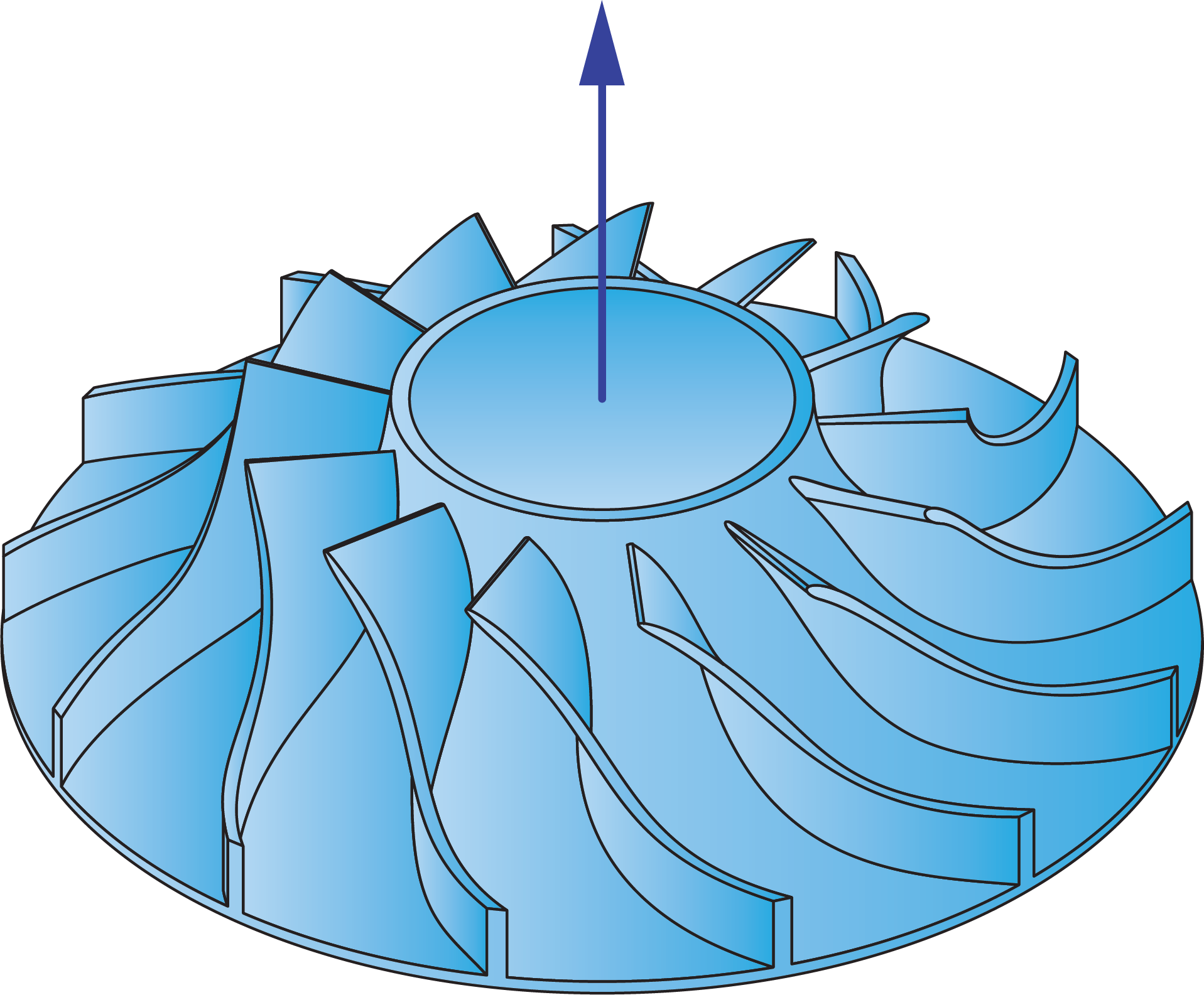
Impeller rotation axisThis parameter enables you to define the rotation axis of the machined impeller part. The rotation axis can be represented by one of the Coordinate System axes (usually the Z-axis) or an arbitrary line defined by picking points on the solid model. |
 |
The Lag angle to cutting direction value enables you to define the tool tilting in the direction of the cutting pass. The Lag angle to cutting direction parameter is measured relative to surface normal.
The Tilt angle at side of cutting direction value enables you to define the tool inclination in the direction determined by Side tilting options. The Tilt angle at side of cutting direction parameter is measured relative to surface normal.
Additional lead angle
This button displays the Additional lead angle dialog box that enables you to define the additional lead angle values at the leading edge, splitter edge and trailing edge.
|
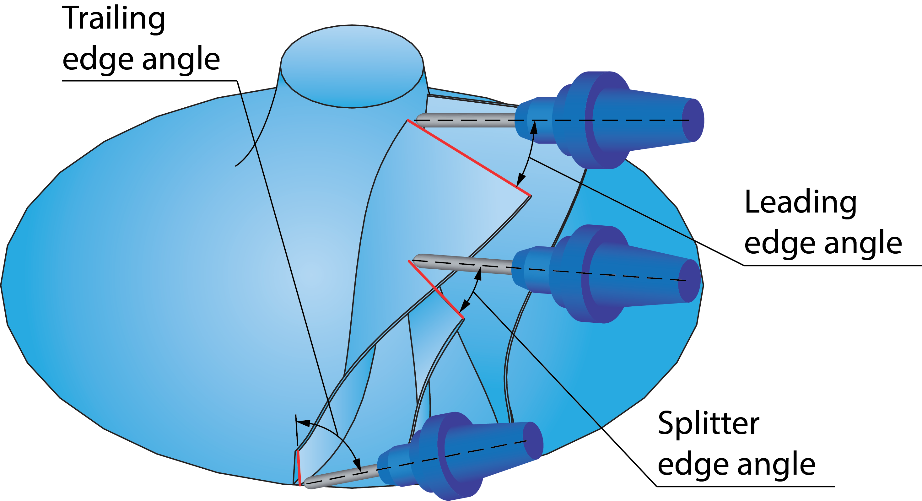 |
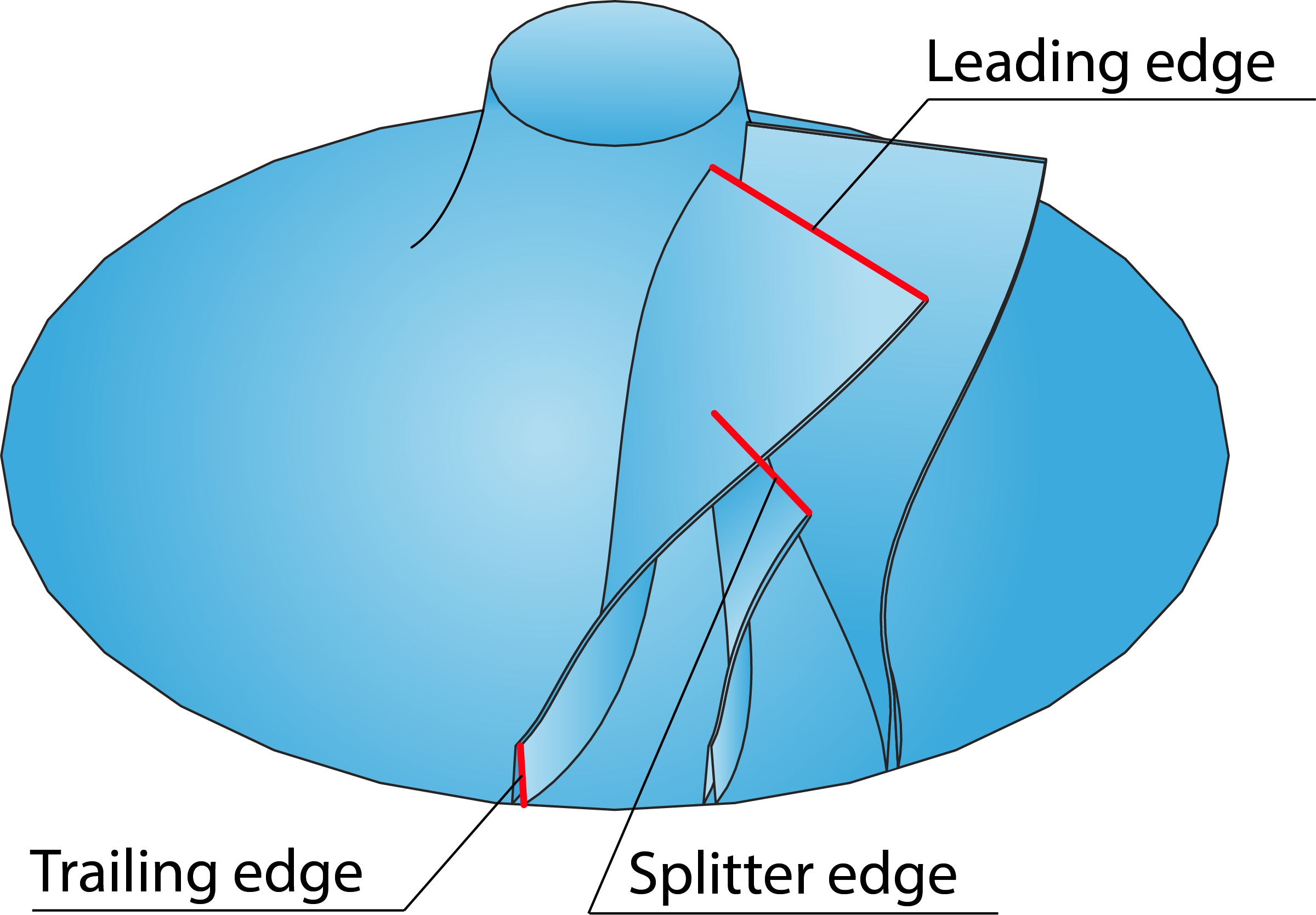
Tilt lines
These lines are defined to apply additional tilting at the leading edge, splitter edge and trailing edge of the impeller blades. These lines must be located and oriented along these edges. |
 |
Approximate
This parameter enables you to calculate the direction vectors for tool path tilting by approximation.