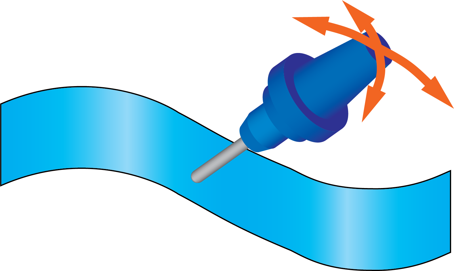
Tilted relative to cutting direction
With this option, SolidCAM enables you to define the tool tilting relative to the cutting direction. |
 |
Side Tilt
When you select the Angle option, you choose the side tilt angle and the tool contact point is defined by the algorithm.
When you select the Contact point option, you choose the contact point on the tool and the tool is aligned tangentially on the surface at the specified contact point. The option of Contact point is not available with End mill, Face mill, Dove tail mill, and Slot mill tools.
Angles when Side Tilt Angle is chosen
When you select the Angle option, you choose the side tilt angle and the tool contact point is defined by the algorithm.
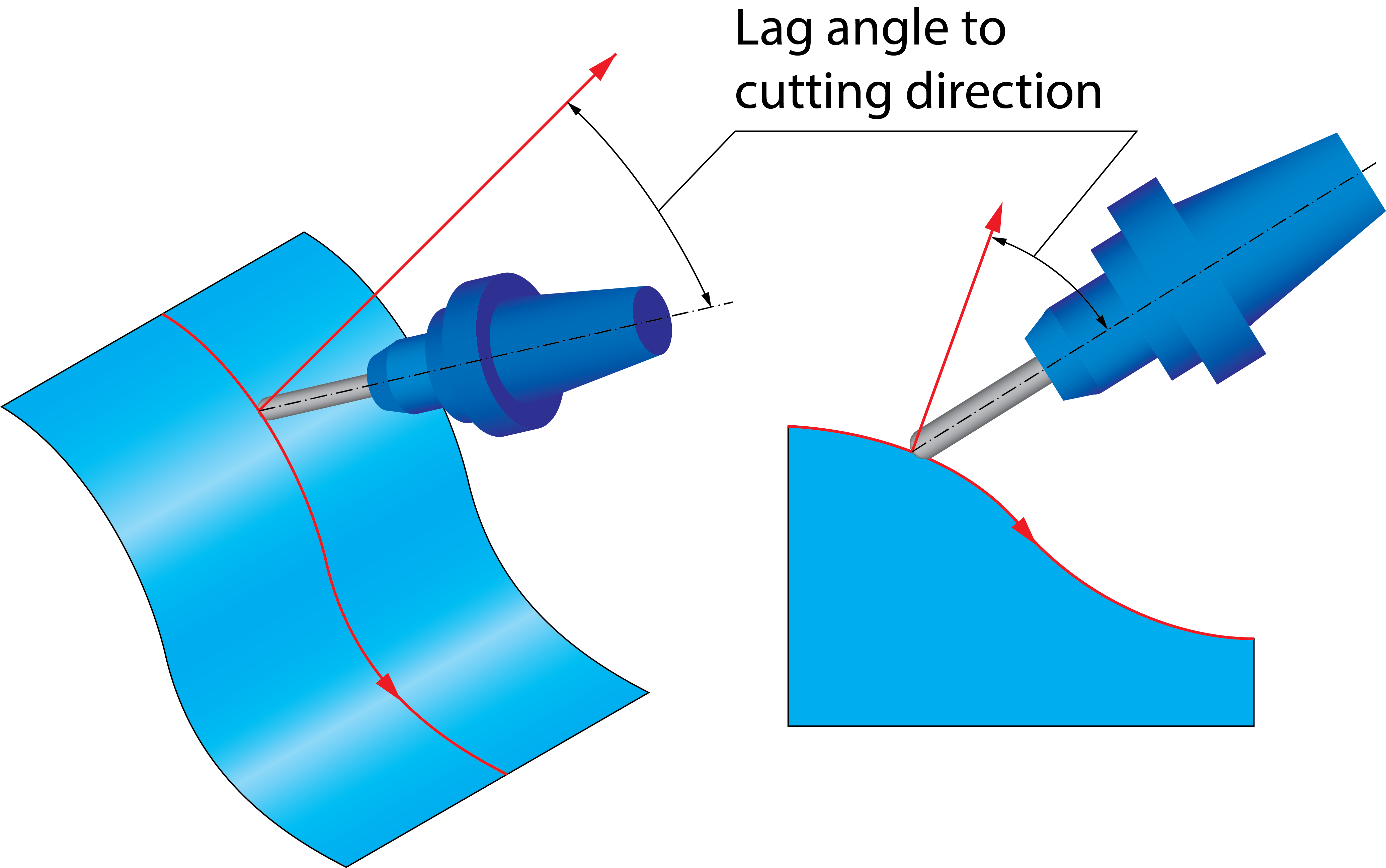
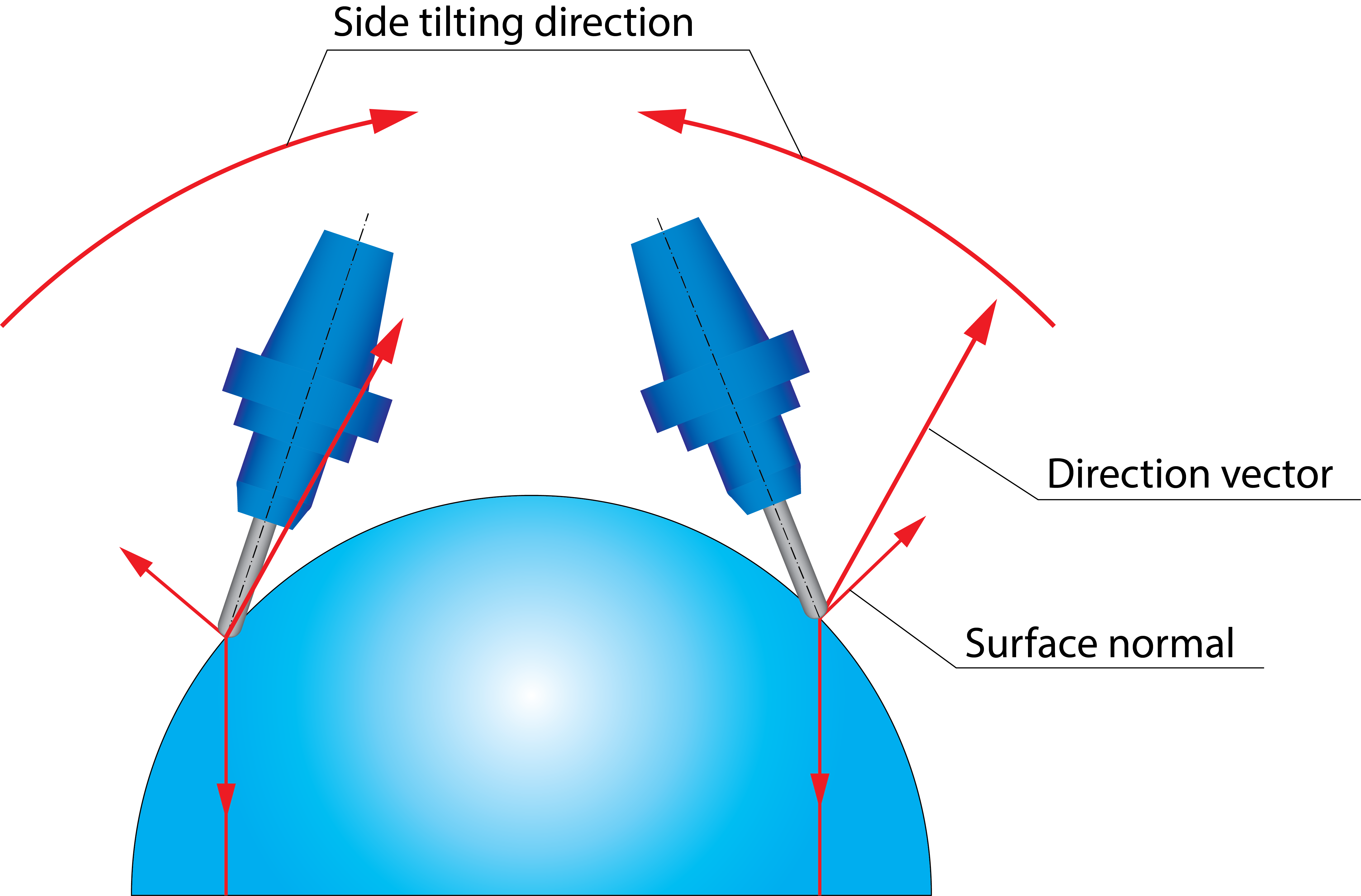
The Lag angle to cutting direction parameter enables you to define the tool tilting in the direction of the cutting pass. The Lag angle to cutting direction parameter is measured relative to surface normal. |
 |
||
|
 |
||
|
 |
||
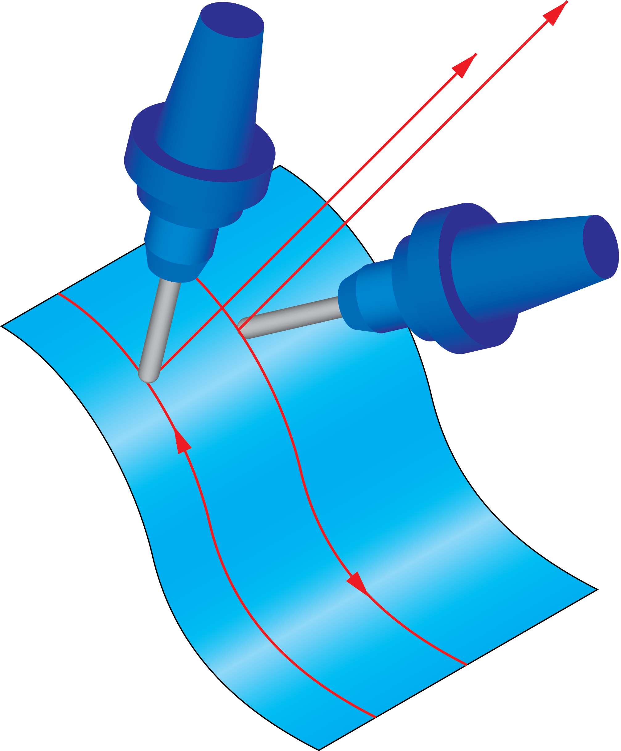
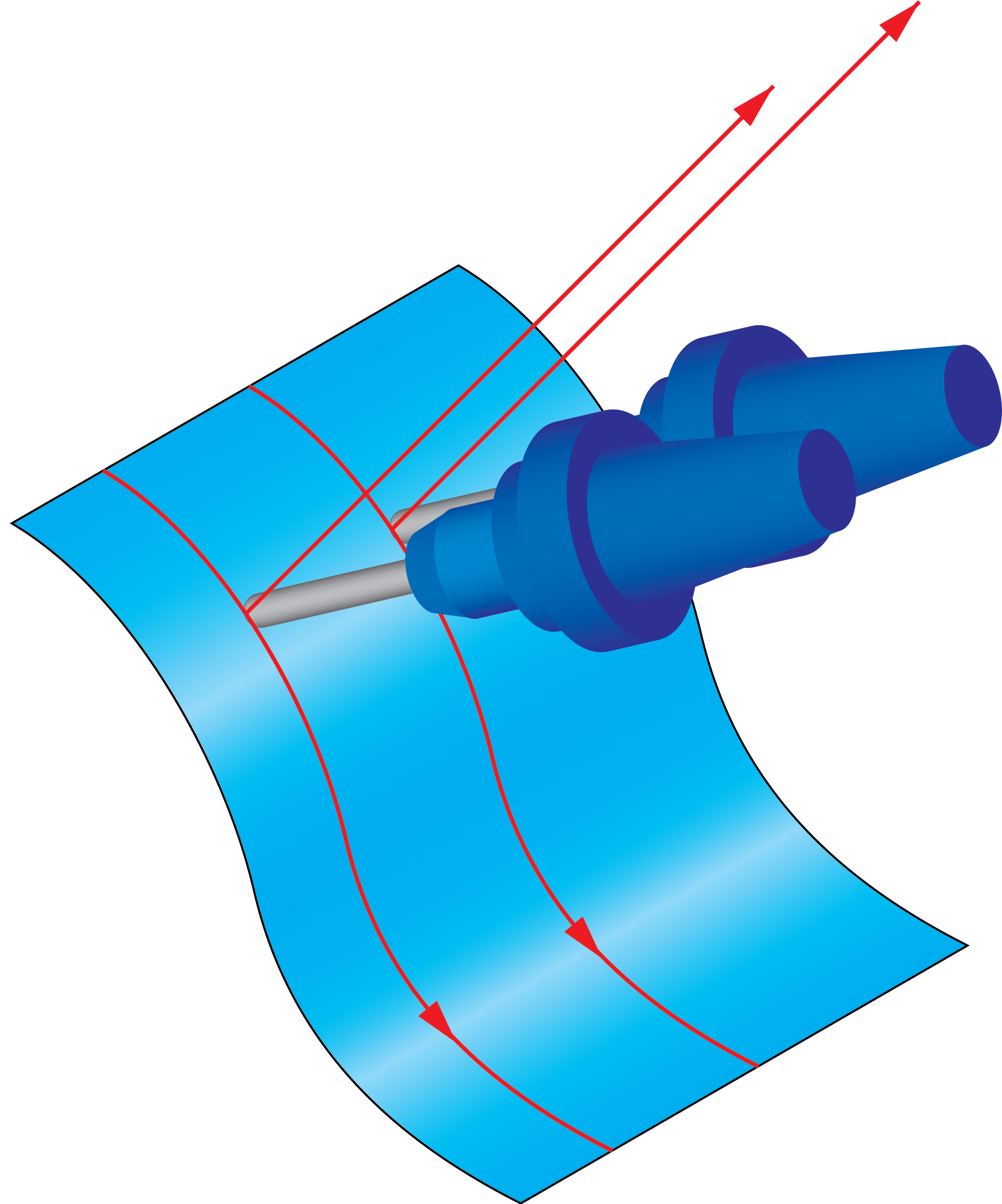
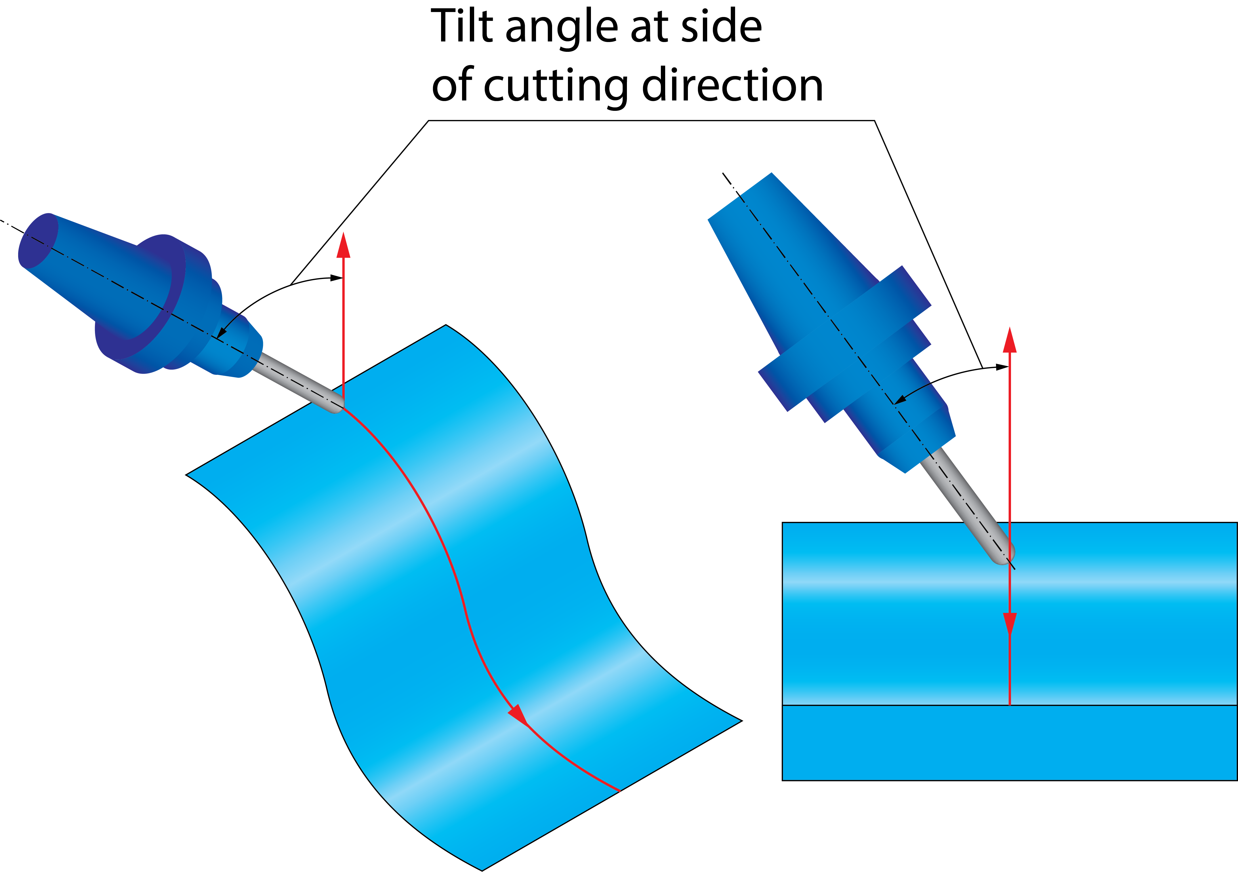
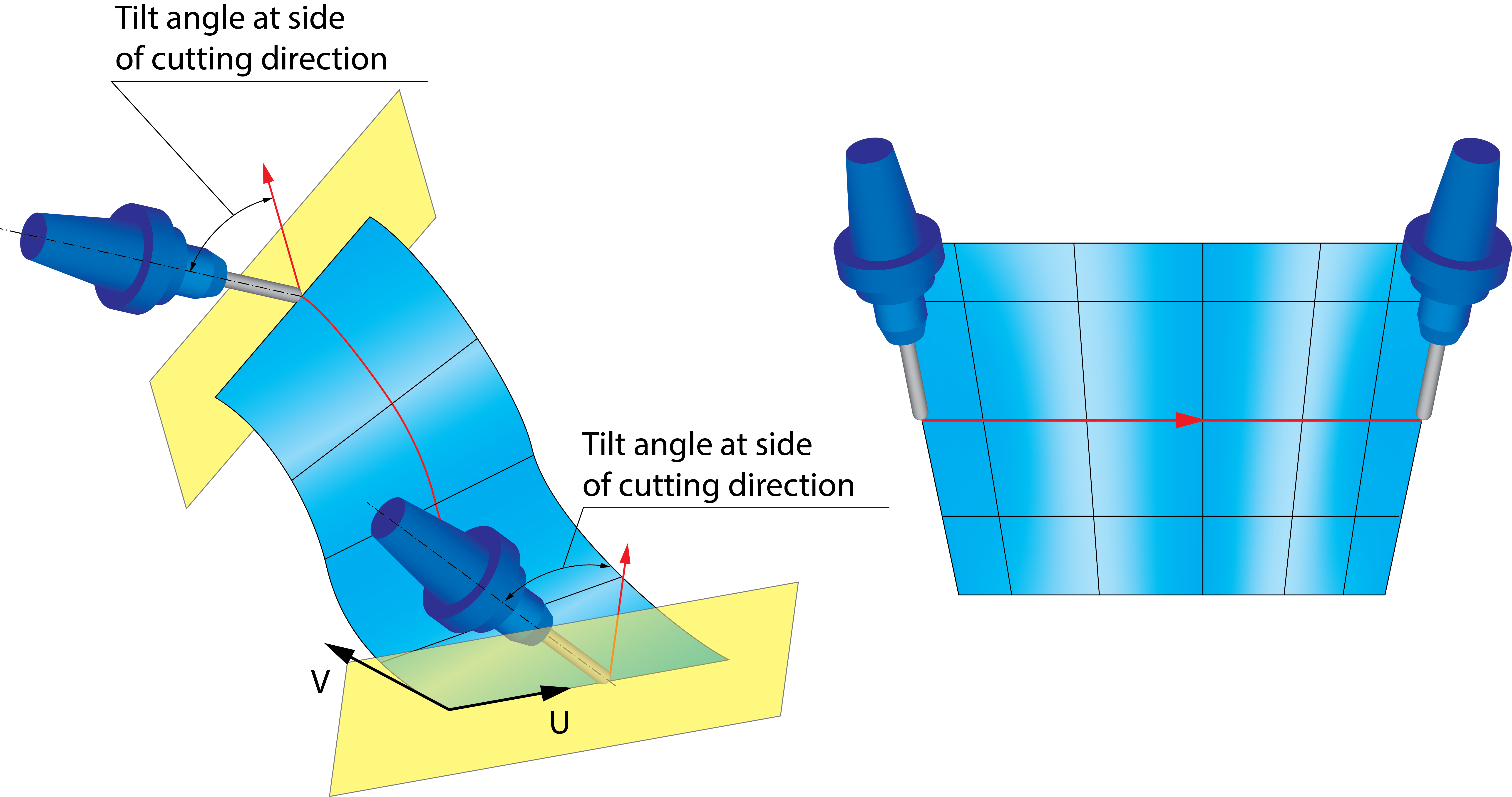
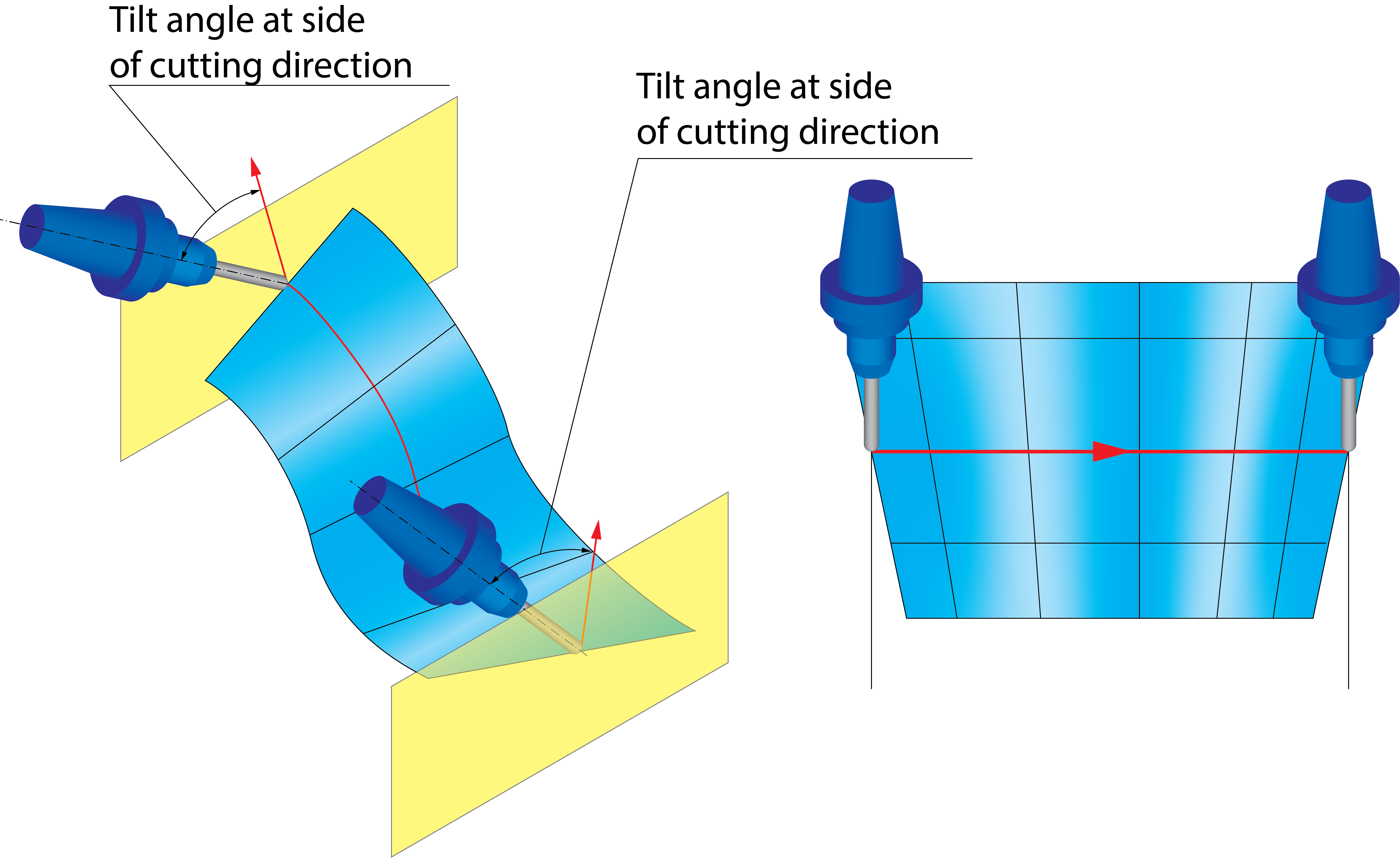
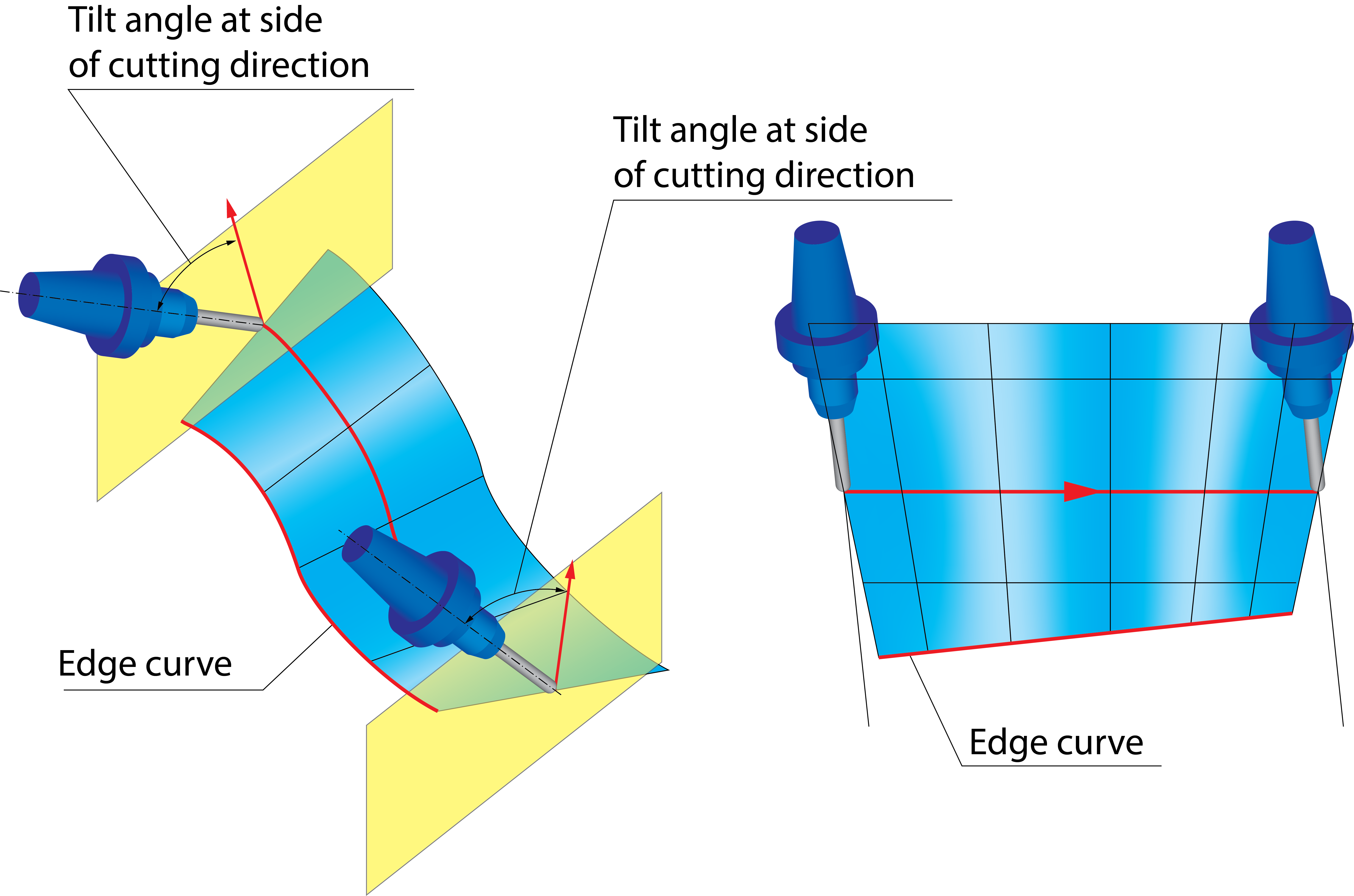
The Tilt angle at side of cutting parameter enables you to define the tool inclination in the direction determined by Side tilting options. The Tilt angle at side of cutting parameter is measured relative to surface normal. |
 |
Angles when Side Tilt Contact point is chosen
When you select the Contact point option, you choose the contact point on the tool and the tool is aligned tangentially on the surface at the specified contact point.
The Lag angle to cutting direction parameter enables you to define the tool tilting in the direction of the cutting pass. The Lag angle to cutting direction parameter is measured relative to surface normal.
Contact point definition
The contact point can be defined in two different ways. When you choose the option of By height, the contact point is defined by the distance from the tool tip to the contact point in the tool axis direction. In the Height in % of flute length field, you can enter the values between 0 and 100 to normalize the distance with the flute length. A value of 0 means that the contact point is directly on the tool tip.
When you choose the option of By line parameter, the contact point is defined by the distance from the tool tip to the contact point along the tool profile. In the Considered profile field, you can enter the values between 0 and 100 to normalize the distance with the length of the considered profile section. A value of 0 means that the contact point is directly on the lower end of the considered profile section.
Considered profile
When the contact point is defined by line parameter, the considered profile section can be specified in three ways:
Full profile- The entire profile from the tip to the end of the upper radius is considered. This option is available for selection with Bull Nose Mill, Ball Nose Mill, Taper Mill, Taper Ball Nose, Lollipop Mill, Barrel Shape, Oval Form, Lens Form and Barrel Taper tools.
Barrel section- Only the profile radius on the tool flank is considered. This option is available for selection with Barrel Shape, Oval Form, and Barrel Taper tools.
Convex tip section- Only the radius on the tool front face is considered. This option is available for selection only with the Lens Form tool.
Use negative side tilt
The tool can be aligned on the defined contact point using a positive or a negative side tilt angle with the same absolute value. Select the Use negative side tilt check box to use the negative side tilt angle.
Side tilt definition
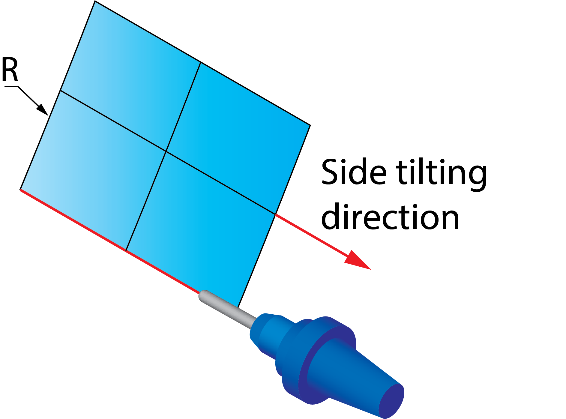
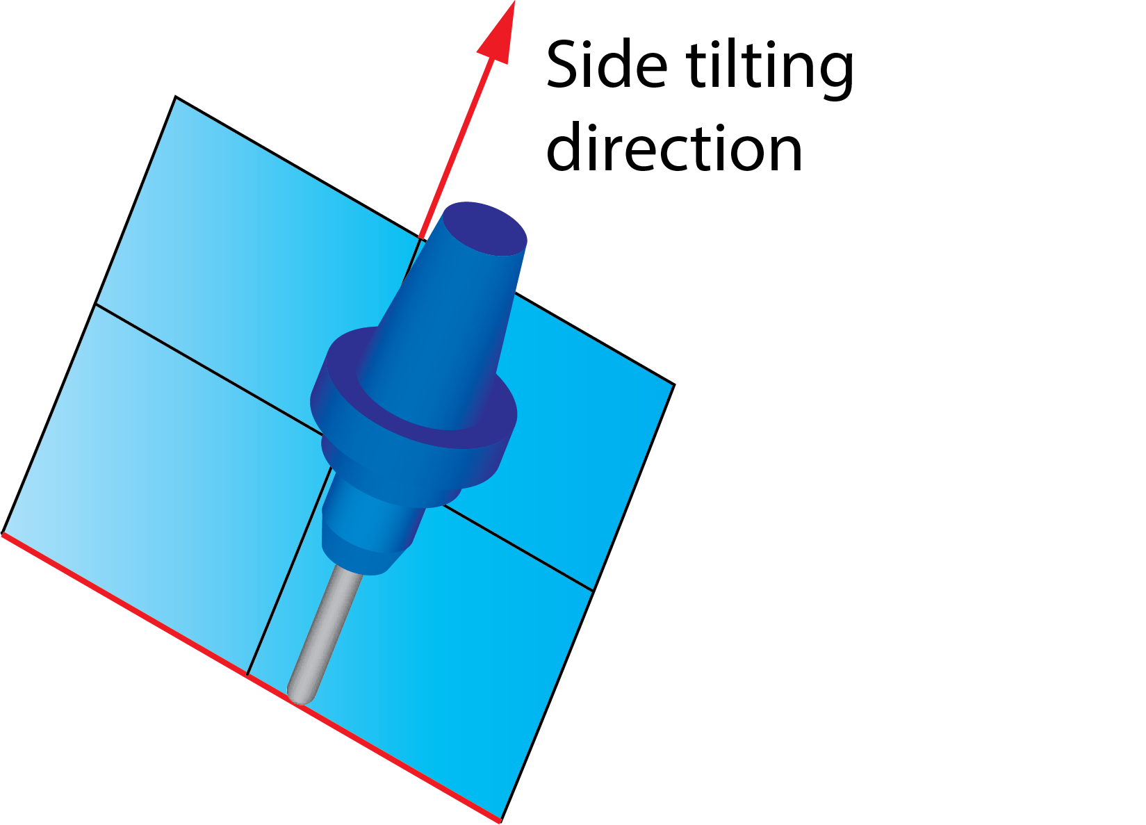
The Side Tilt tab allows you to define the Side Tilt definition parameters. SolidCAM enables you to choose the following options to define the direction of the side tilting:
Follow surface ISO Lines directionThe direction of the side tilting is chosen according to the direction of the U- and V-vectors of the drive surface.
|
 |
Orthogonal to cut direction at each positionThe plane of the side tilting is orthogonal to the tool path direction for each cutting position. |
 |
||
Orthogonal to cut direction at each contourThe direction of the side tilting is determined by an orthogonal line to a tool path segment. SolidCAM approximates the orthogonal vectors in all tool path positions of the segments according to the Approximate option:
|
|||
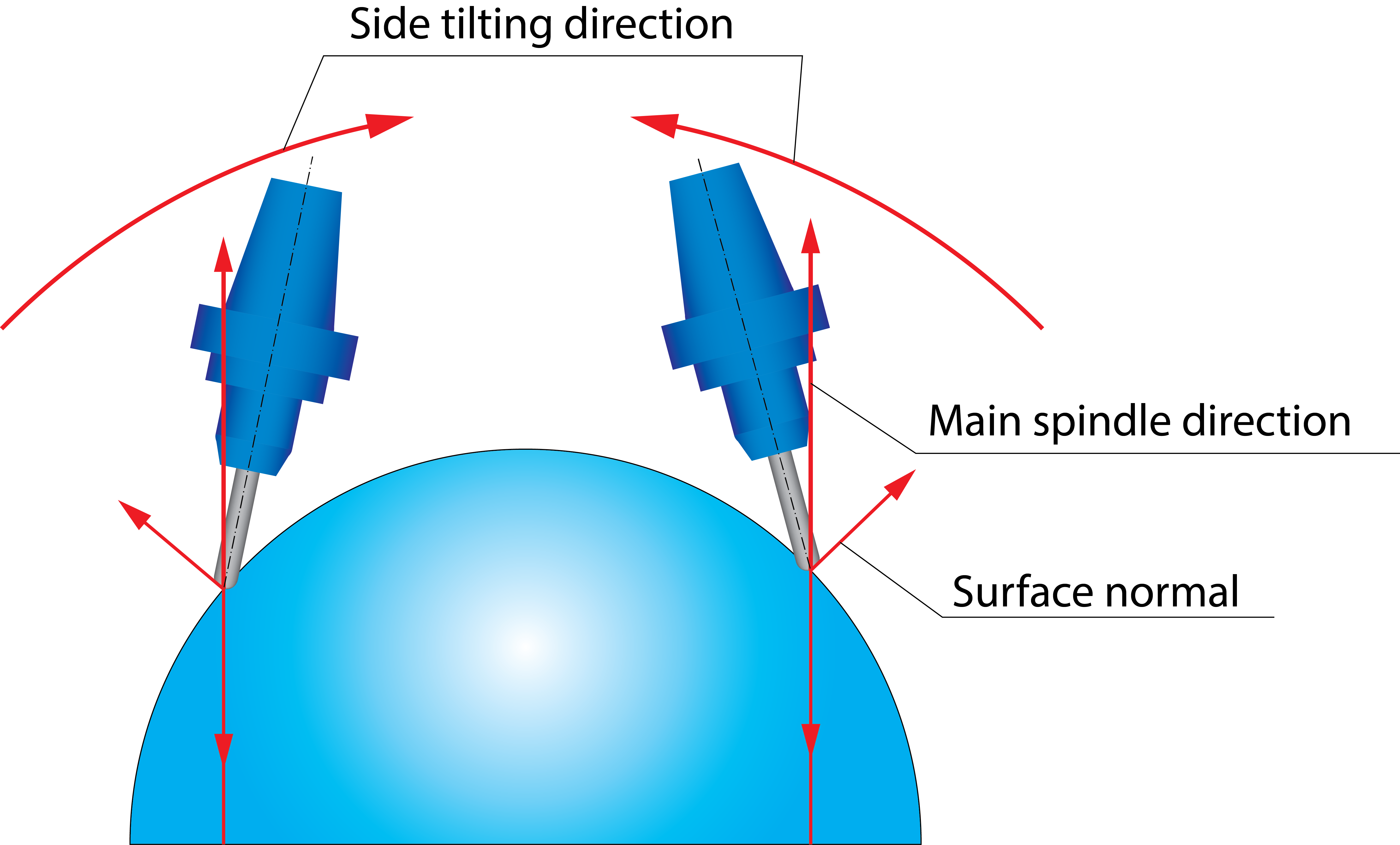
Use spindle main directionSolidCAM uses the spindle main direction vector definition as the reference for the side tilting direction. The side tilting is always performed in the direction defined by the spindle main direction vector. |
 |
||
Use user-defined directionSolidCAM enables you to specify the reference vector to determine the side tilting direction. The side tilting is always performed in the direction defined by user-defined vector. Click Data to display the Direction dialog box that enables you to specify the direction point for the vector. The vector starts from the Coordinate System origin and points to the specified location. |
 |
||
Orthogonal to edge curveWith this option, the plane of the side tilting is orthogonal to the edge curve at each cutting position.
|
 |
||
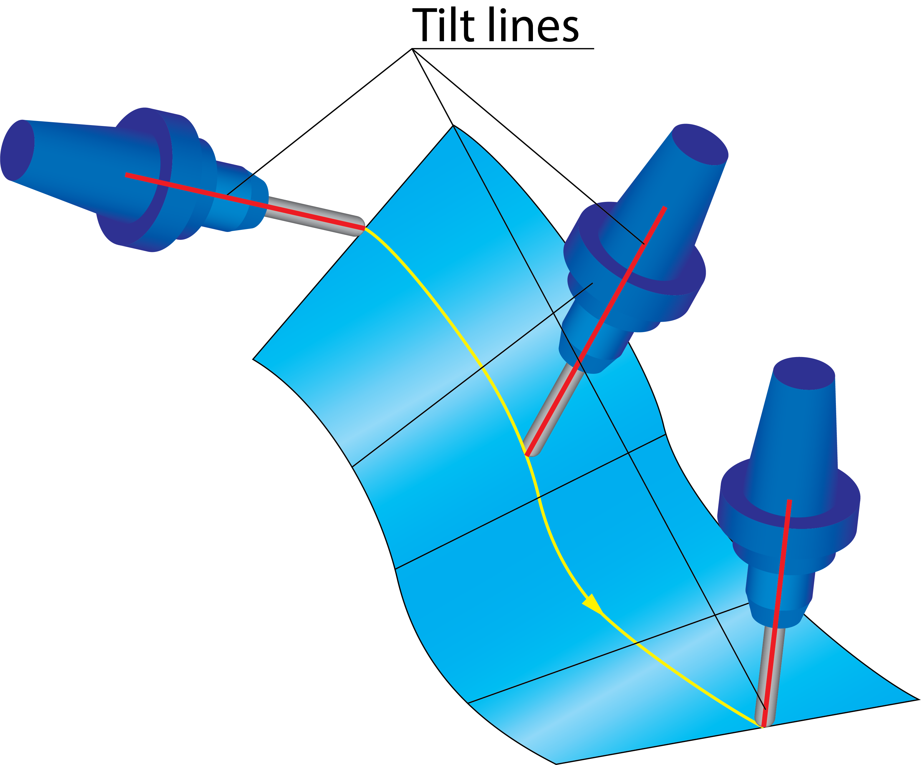
Use tilt line definitionThis option enables you to define the direction of the side
tilting by a number of lines. The Tilt
lines section enables you to choose the lines geometry
from a list or define a new one with the The Tilting lines maximum snap distance parameter defines the maximum distance between tilt line end points and the machining contour. When tilting is applied to a contour, only lines within this distance are used, while other lines that are far from the contour are ignored. Note that the tilt lines are snapped to the machining contour via the shortest distance from the line to the contour.
|
 |
||
Advanced options for tilting relative to cutting direction
SolidCAM enables you to define a number of advanced parameters for the side tilting options.
|
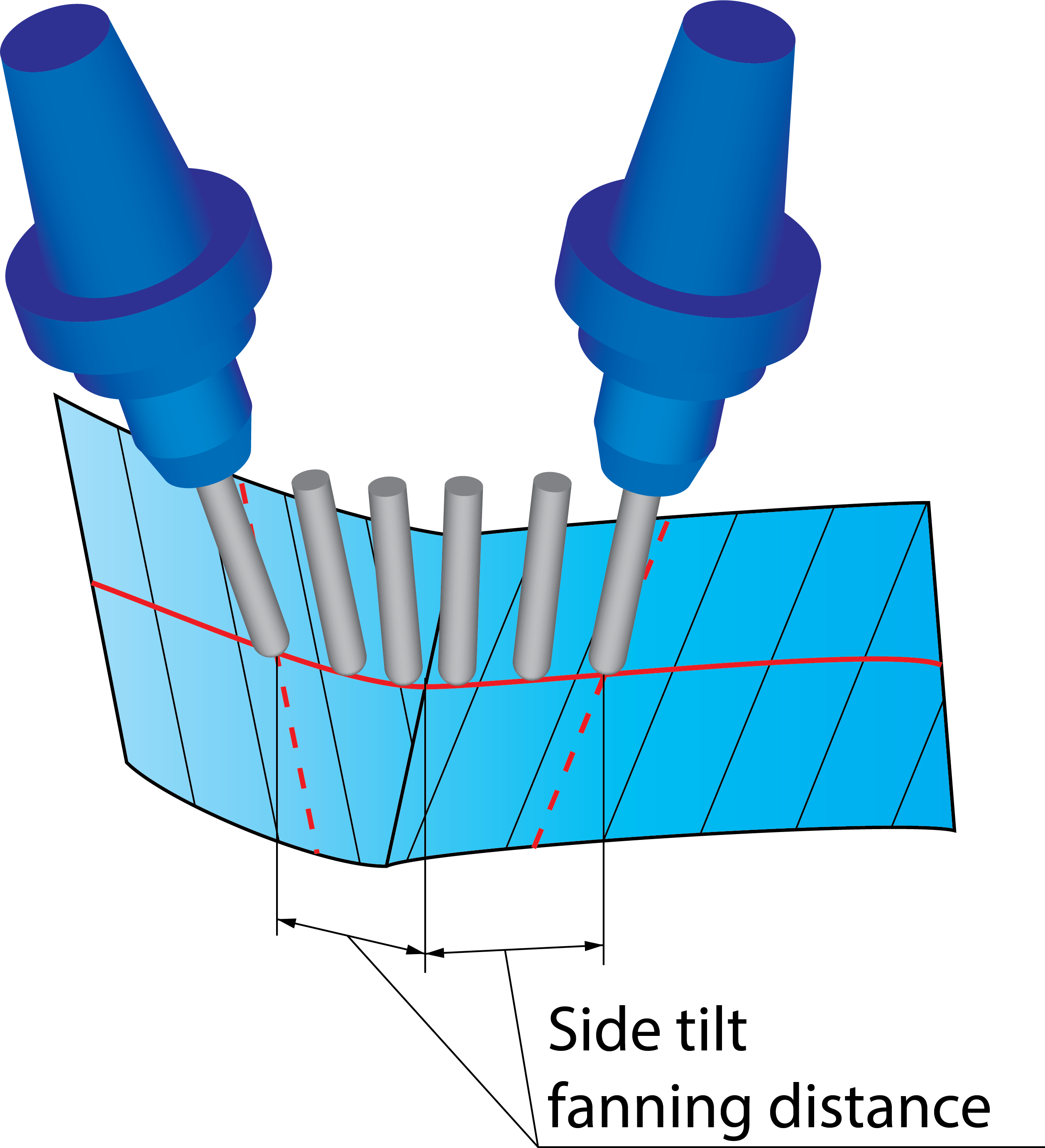
This option is available only when the Follow surface ISO Lines direction option is used for the Side tilt definition. Using this option, SolidCAM enables you to control the side tilting direction at the intersection of two surfaces with different isometric directions. In such intersection areas, SolidCAM performs smooth transition of the side tool tilting taking into account the different direction of ISO vectors. The Side tilt fanning distance parameter defines the distances from the surface intersection where the transition of side tilting directions is started. |
 |
||
|
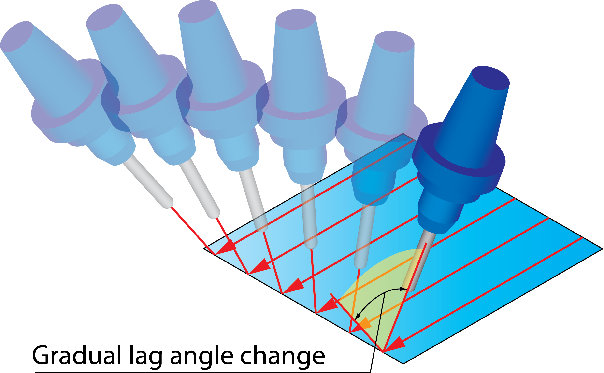
SolidCAM enables you to change the lag angle gradually along the tool path. The lag angle is changed for each cutting pass; the final change of the lag angle at the end of the tool path is determined by the Gradual lag angle change value. For each cutting pass, the increment of the lag angle is equal to the Gradual lag angle change value divided by the number of cutting passes. This option is available for all the options used for Side tilt definition.
For example, the Lag angle to cutting direction parameter is set to 5°. The Gradual lag angle change value is set to 10°. In this case, the tool path is started with the lag angle of 5° and finished with the lag angle of 5°+10° = 15°. In the middle of the tool path, the lag angle is 5° + 0.5*10° = 10°.
|
 |
||
|
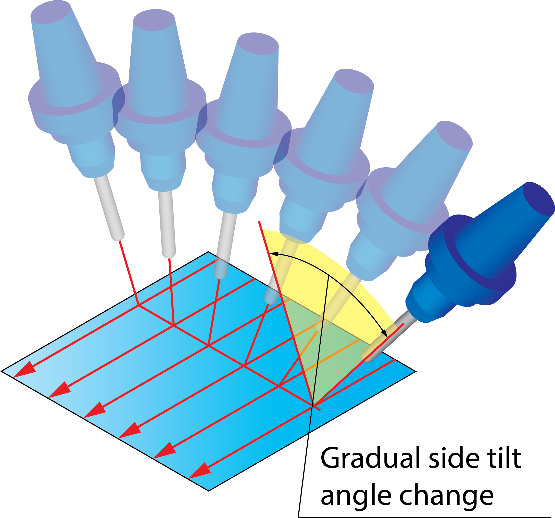
SolidCAM enables you to change the side tilt angle gradually along the tool path. The side tilt angle is changed for each cutting pass; the final change of the side tilt angle at the end of the tool path is determined by Gradual side tilt angle change value. For each cutting pass the increment of the side tilt angle is equal to the Gradual side tilt angle change value divided by the number of cutting passes. This option is available for all the options used for Side tilt definition.
For example, the Tilt angle at side of cutting direction parameter is set to 5°. The Gradual side tilt angle change value is set to 10°. In this case, the tool path is started with the side tilt angle of 5° and finished with the side tilt angle of 5°+10° = 15°. In the middle of the tool path, the side tilt angle is 5° + 0.5*10° = 10°.
|
 |
||
|
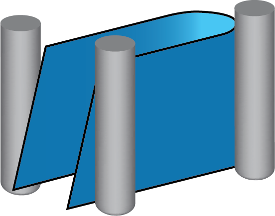
SolidCAM enables you to automatically recognize and machine ruled surfaces (a Ruled surface is a surface that can be swept out by moving a line in space) by the Swarf machining technology. With this technology, the machining is performed by the tool side that has a linear contact with the machined ruled surface. When the Follow surface ISO Lines direction option is used, SolidCAM automatically chooses the direction of straight lines (rulings) of the ruled surface as the direction of the side tilting. Sometimes the surfaces seem to be planar but actually have a curvature of large radius in one direction. SolidCAM considers these surfaces as ruled and uses rulings as the direction of side tilting causing wrong tool orientation. On the illustration, the horizontal isometric direction is defined by a straight line; the vertical isometric direction also seems to be straight but actually has a large radius of curvature. The surface is considered as ruled. The tool side tilting direction is chosen according to the direction of the horizontal ISO line, resulting in a wrong tool orientation (side tilting angle is 90°).
|
 |
||
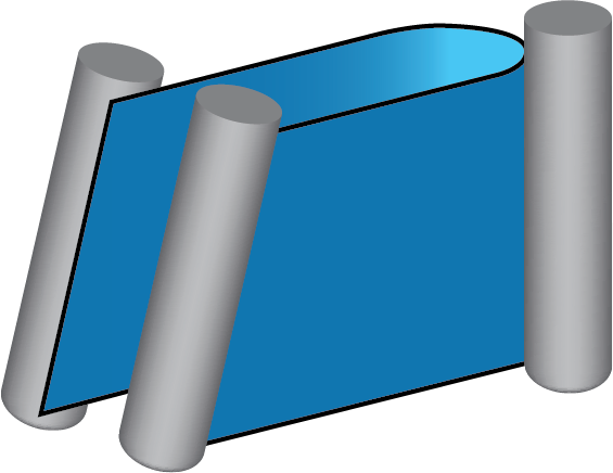
The Ruled surface radius limit parameter enables you to limit the maximum radius of curvature of ISO lines for a surface to be considered as ruled. All the curved ISO lines with a radius greater than the specified value are considered as straight lines. The face is not considered as ruled and machining is performed with a proper side tilting. This option is available for all the options used for Side tilt definition. |
 |
||
|
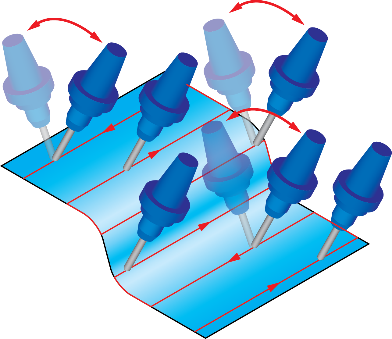
This option enables you to change the direction of the side tilting for the tool path generated with the Zigzag cutting method. When this check box is not selected, the direction of the side tilting is the same for all cutting passes. When this check box is selected, SolidCAM changes the side tilting direction to the opposite when the cutting pass direction is changed. This checkbox is available only when the Cutting method is selected as Zigzag on the Sorting tab of the Tool path parameters page.
|
 |
||
|
Although the tool axis will be aligned to the isometric direction, the orientation at the start and end of the blade will be aligned to its surface edge, even if this edge does not follow the isometric direction. This option can be used for impeller blade machining.
|
|||
|
|
Align tool axis to planar surface edges check box is not selected
|
Align tool axis to planar surface edges check box is selected |
|
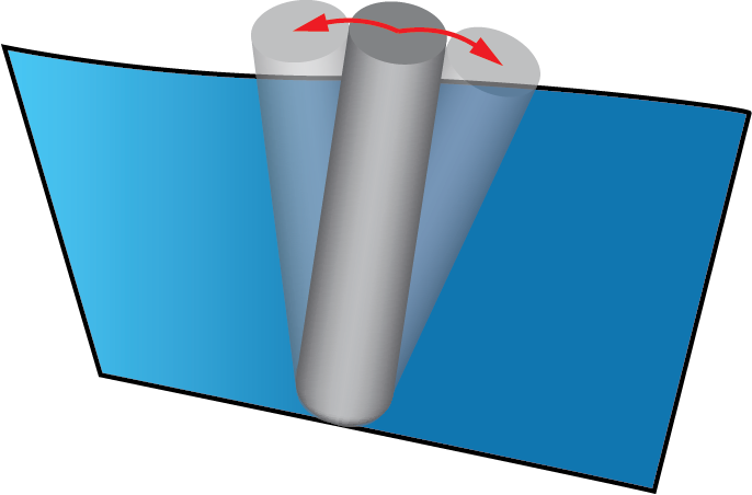
This option enables you to optimally adjust the tool tilting for swarf machining of twisted ruled surfaces. The idea is to get a contact line between the tool and the surface, which is nearly impossible when the surface is twisted. When the Improve side tilt definition for twisted surfaces check box is selected, the system determines an optimal surface alignment for the swarfed tool path to obtain better swarfing and better line contact between the tool and the surface. This check box is available for all the options used for Side tilt definition.
|
 |