Modify
The Modify tab enables you to define the parameters that affect the tool path in various ways. This tab is visible only when the Advanced check box is selected. This tab is unavailable for Projection strategies.
Surface edge merge distance
SolidCAM generates first tool paths for individual surfaces. Then they are merged together to form the complete tool path. The decision about merging is based on the Surface edge merge distance parameter. If all surface paths on a tool path slice are merged, SolidCAM checks if a closed surface path can be built by connecting the start to the end. This decision is made based on the Surface edge merge distance parameter meant to deal with minor gaps between surfaces edges.
The Surface edge merge distance parameter can be defined either as a numeric value (the As value option) or as a percentage of the tool diameter (the As % of tool diameter option). In both cases, this limit value must be greater than or equal to the Cut tolerance value.
Apply outer sharp corners
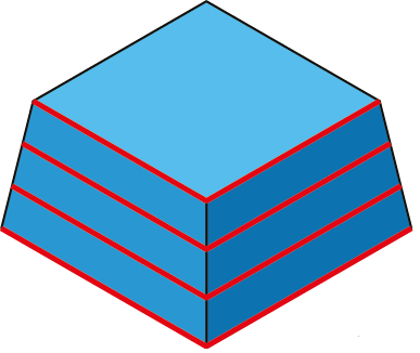
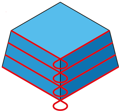
This option enables you to perform machining of adjacent outer edges of the model in such a manner that the sharpness of the corners is preserved. Instead of rolling around the edge that results in rounding of the corner, the tool path is extended for both edge surfaces, and the extensions are connected with a loop, resulting in an absolutely sharp machined corner. |
 |
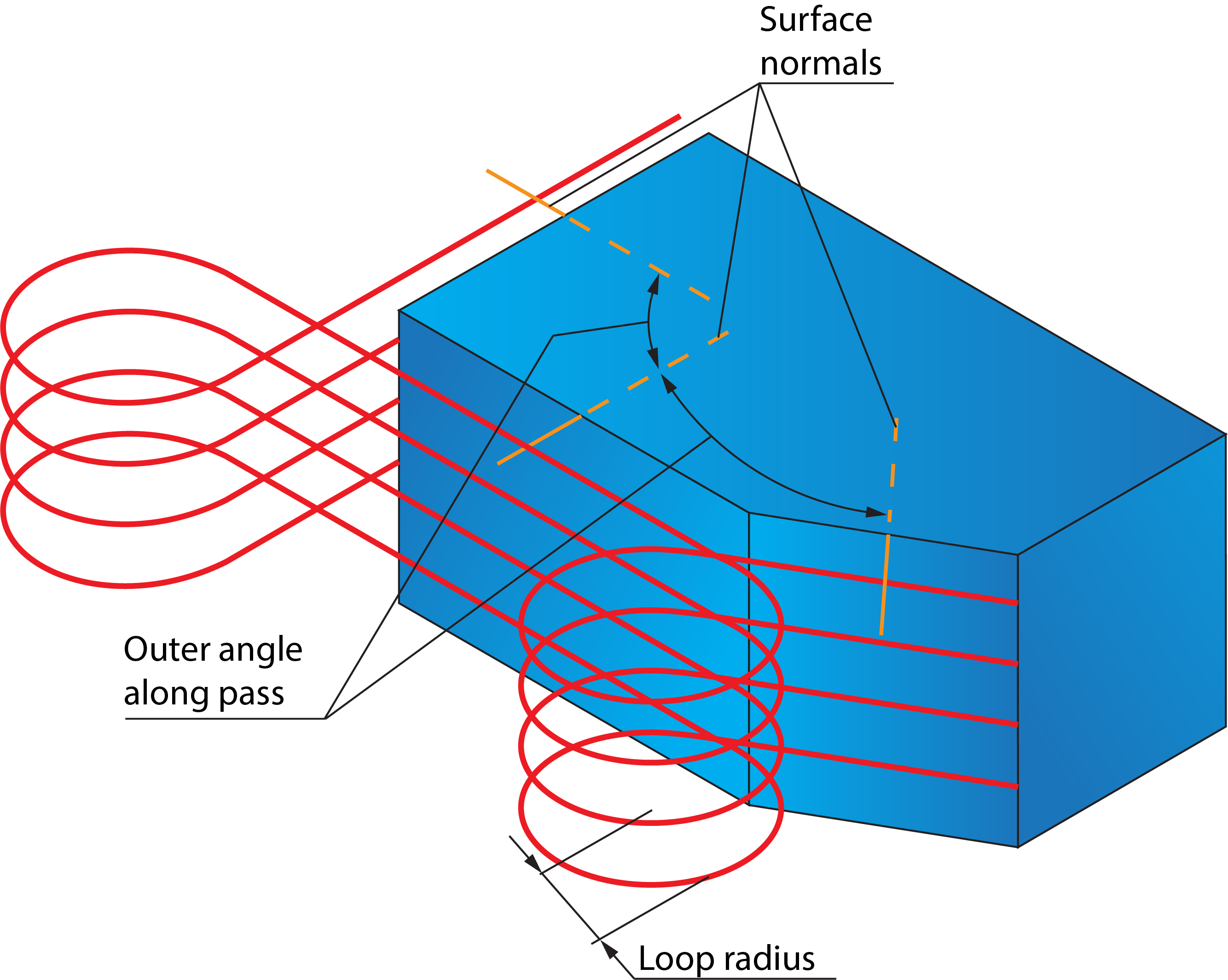
When this check box is selected, you can define the parameters and conditions for corner looping. The Outer angle along pass parameter defines the maximal value of the angle between two normals to the surfaces of the corner to enable looping; for angles greater than defined, loops will not be performed. |
 |
The Loops radius value defines the radius of the loop to be performed.
|
 |
|
When the Loops radius is smaller than the radius of the tool, loops will not be performed. |
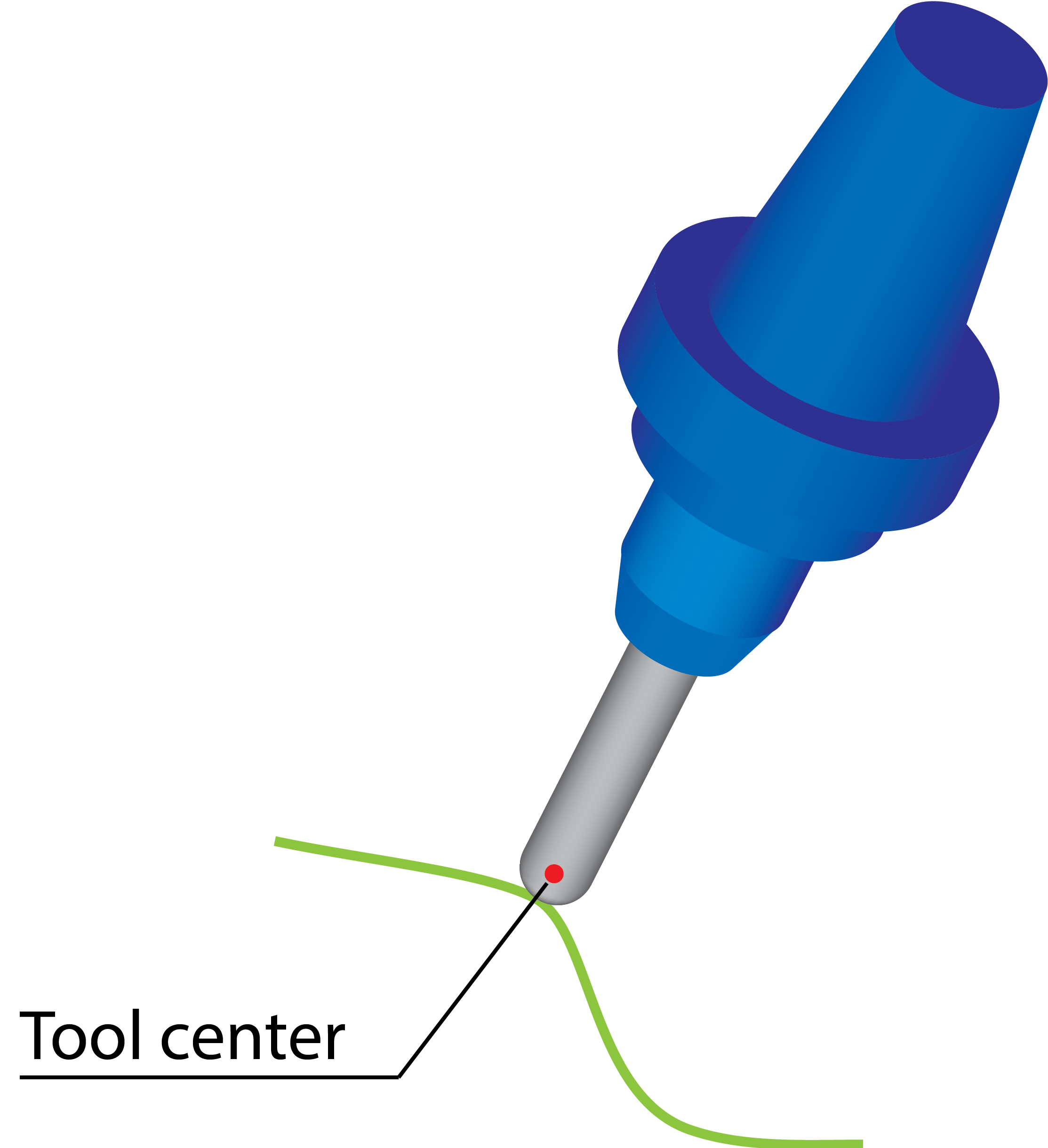
3D Tool compensation
When this check box is selected, the tool compensation options of the CNC-controller are used in the GCode. The output tool path is recalculated according to the following formula:
C = T + R * N,
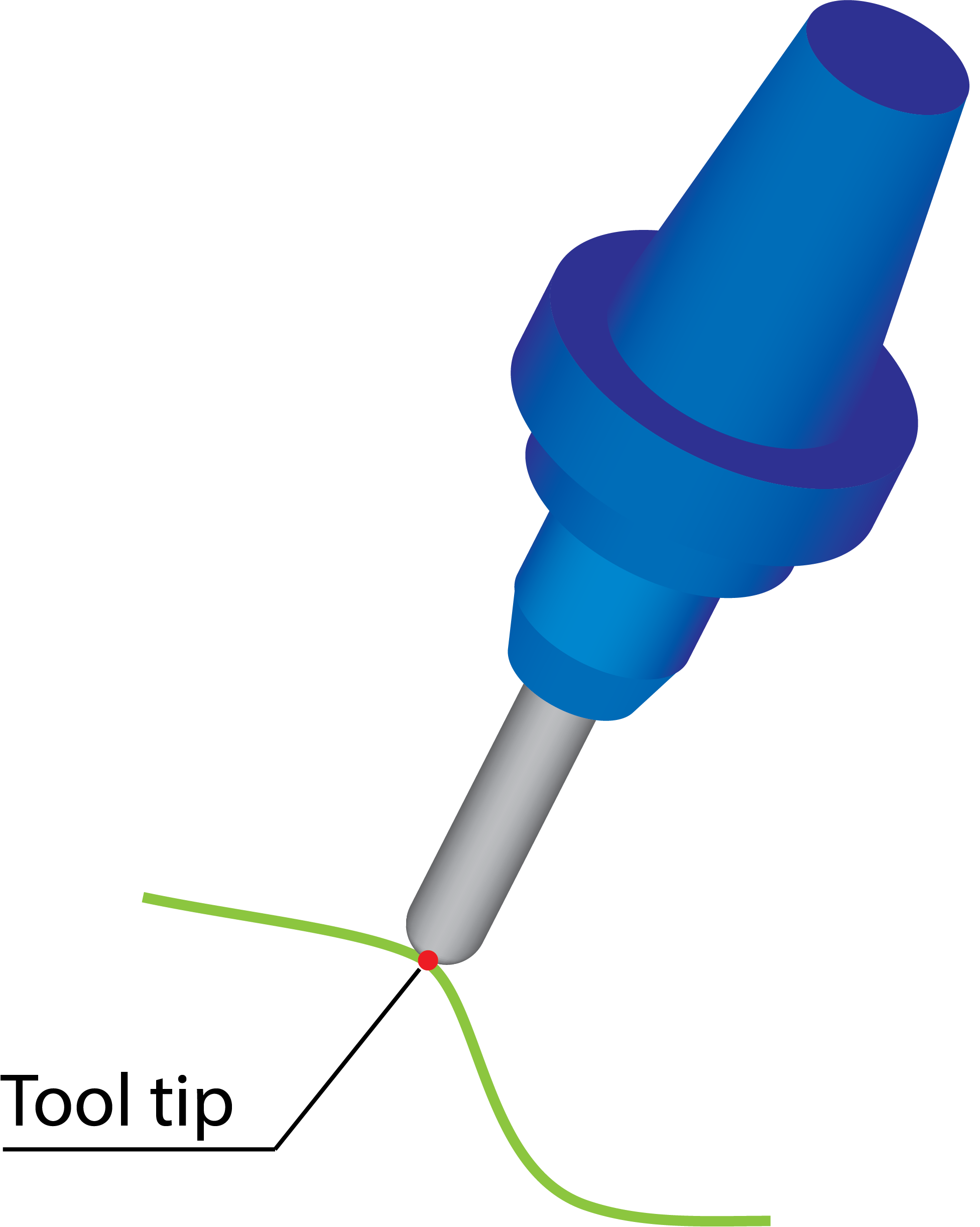
where C is a new coordinate of tool center, T is the coordinate of tool tip, R is the corner radius of the tool, and N is the tool vector.
When the Tool Tip option is chosen, the tool path is calculated according to the tool tip, and the type_offset_3D:tool_tip command is output to the GCode under compensation_3d. |
 |
When the Tool Center option is chosen, the tool path is calculated according to the tool center and the type_offset_3D:tool_center command is output to the GCode under compensation_3d. |
 |
Smooth ToolPath
The option of Smooth ToolPath enables tool path rounding of corners of all passes thereby providing smooth motions in tight areas. When the Smooth ToolPath check box is selected, Smoothing Distance and Detection Angle the two parameters that control tool path smoothing are enabled.
Smoothing Distance- Smoothing distance is the distance from the rounding of tool path to the sharp edge of tool path.
Detection Angle- Detection angle is the angle at the sharp edge of the tool path. Tool path below this detection angle value is not smoothed during the machining process.
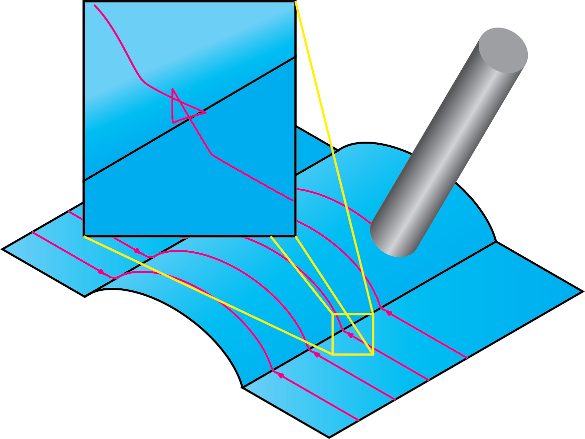
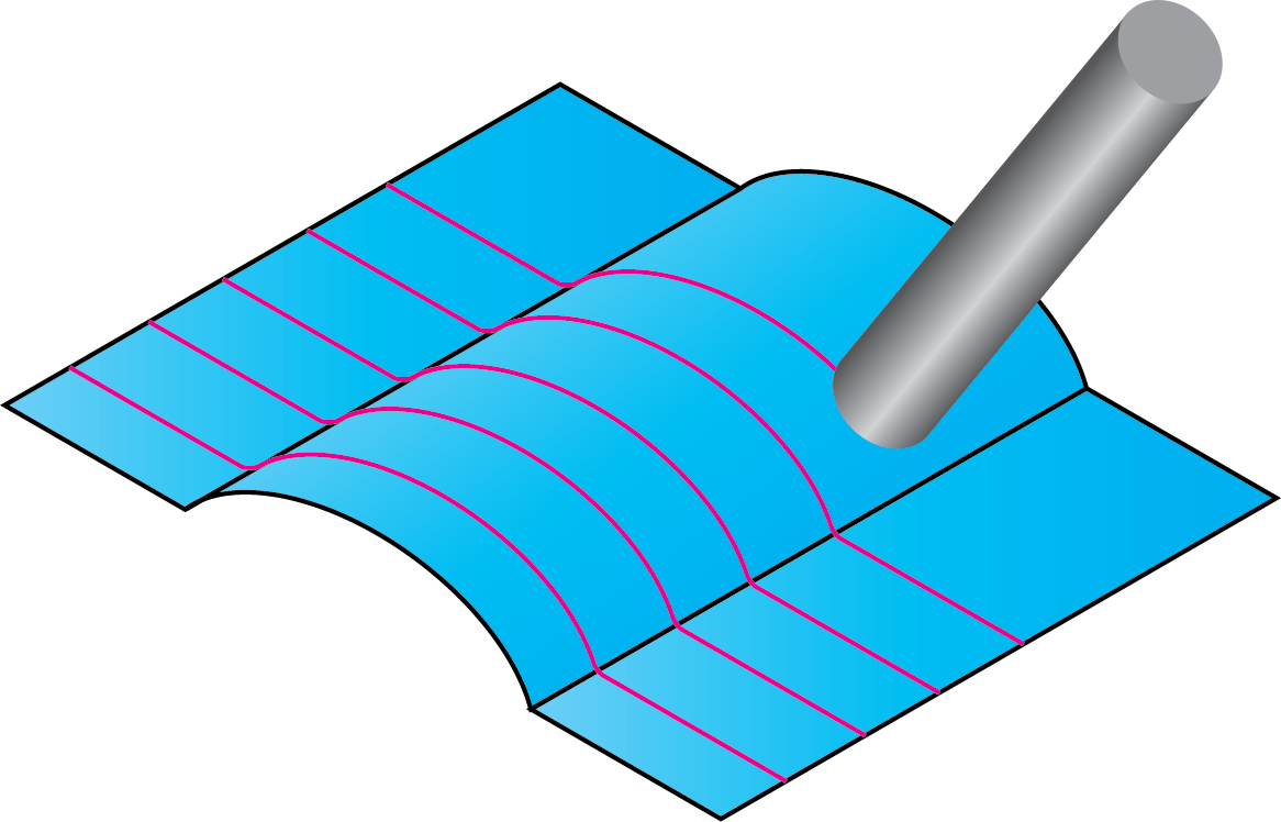
Round corners
In some cases, the Sim. 5-Axis tool path contains unnecessary fish tail movements in sharp corners or in small radius areas.
|
 |
||
Using the Round corners option, you can avoid such movements and generate a smoother tool path. Click Round corners. The Round surfaces by tool radius dialog box is displayed enabling you to define the boundaries. The tool path rounding is performed in the direction of passes with a radius equal to the sum of the tool corner radius and the specified Additional radius value.
|
 |
Angle range
SolidCAM enables you to define the cutting area by the surface inclination angle.
Click Angle range. The Parameters to Define Shallow and Steep Areas dialog box is displayed. This dialog box enables you to define parameters determining the steep/shallow area to be machined.
View direction
SolidCAM enables you to define a vector from where the slope angle start and end are referenced. SolidCAM enables you to choose one of the Coordinate System axes (X-axis, Y-axis and Z-axis) or define a vector by an end point (the start point is automatically considered to be located in the Coordinate System origin).
|
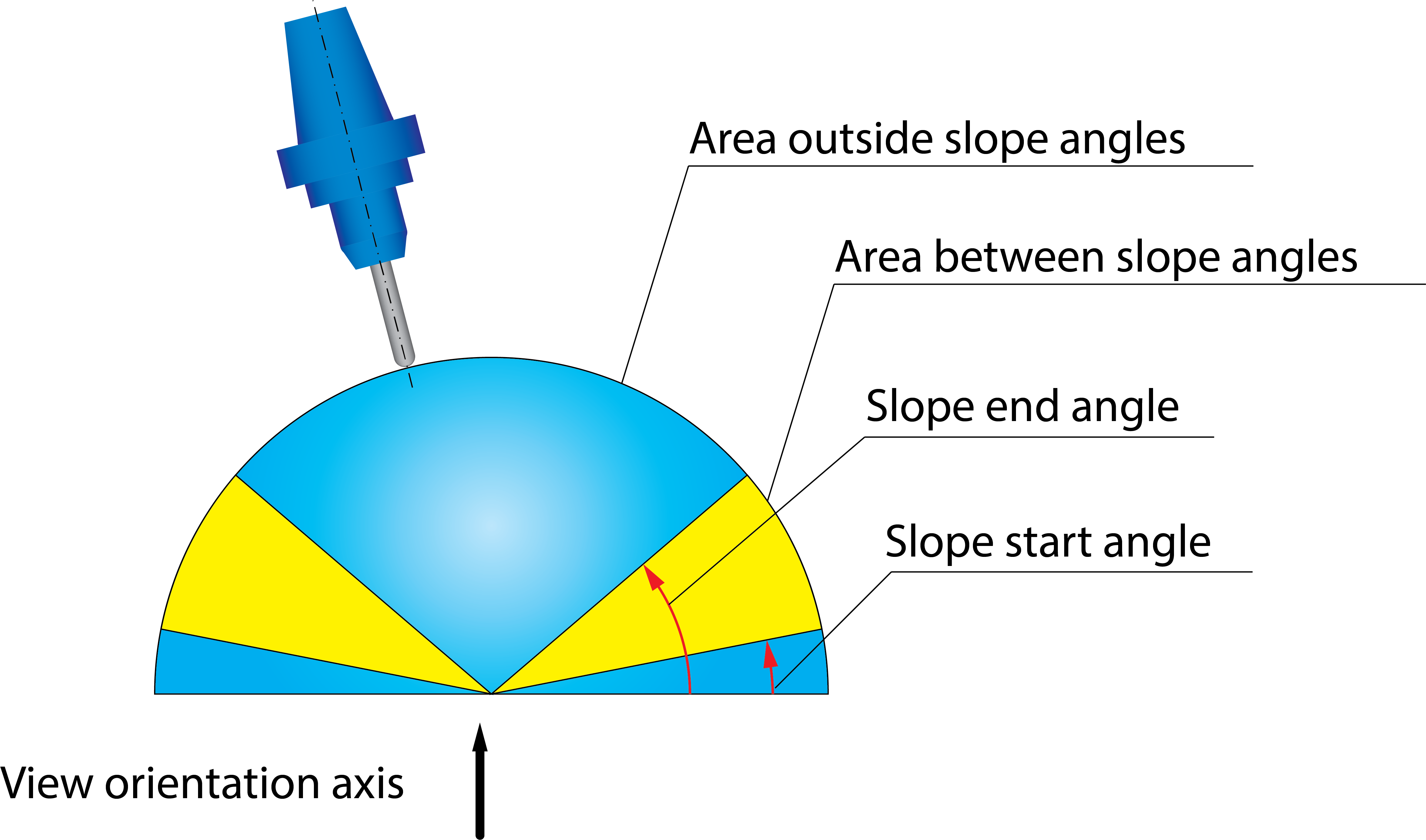 |

The Slope angle start and Slope angle end parameters define the limit angles around the View direction vector.


This option enables you to determine the area to be machined.
| When the Machine between slope angles option is chosen, the machining is performed only at surfaces with inclination angles within the range defined by Slope Start and Slope End angles. |  |
| When the Machine outside slope angles option is chosen, the machining is performed only at surfaces with inclination angles outside the range defined by Slope Start and Slope End angles. |  |
|
The cutting area calculation is purely based on surface contact points. In other words, some portions of the surface geometry are virtually trimmed in order to split the part into shallow and steep regions. |
|
The Angle Range option can be deactivated by clicking the corresponding check box. |
Extend/Trim
SolidCAM enables you to extend/trim the tool path along the cutting direction (Tangential extensions) and across the cutting direction (Side extensions).
The Extend/Trim button displays the Extend/Trim dialog box, which enables you to define the tangential and side extension distances.
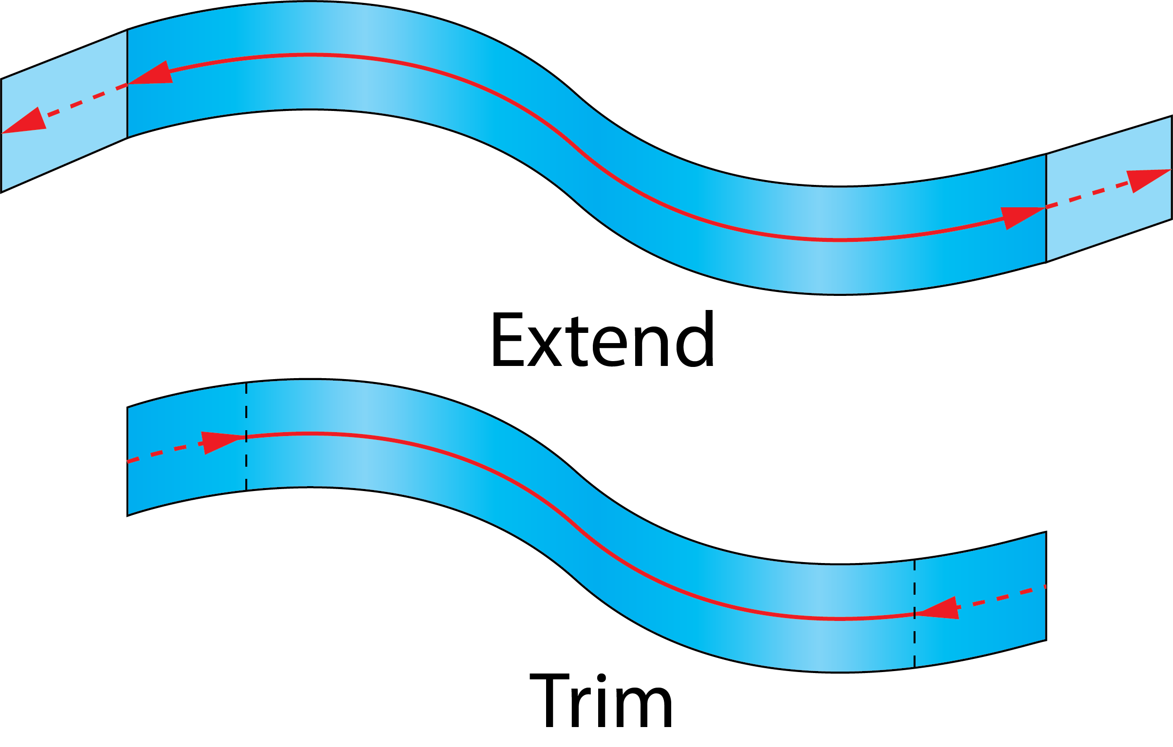
Tangential extensions
SolidCAM virtually extends or trims the drive surface along the cutting direction and generates the tool path for it. In the case of extending a tool path, the tool moves to the specified distance beyond the end of the surface. In the case of tool path trimming, the tool stops at the specified distance before the surface boundary and moves to the next cut.
|
 |
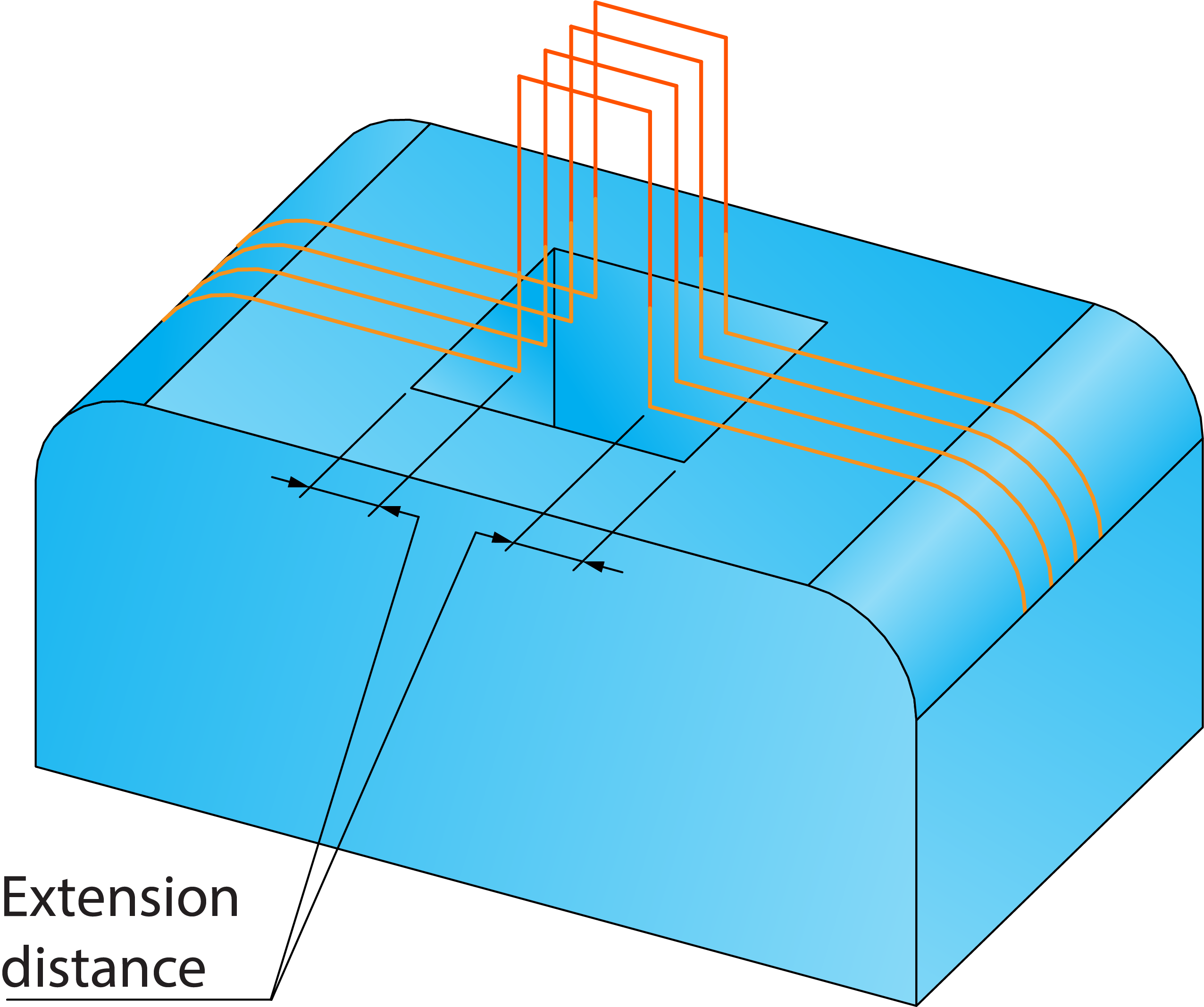
Extend/Trim gaps
This option enables you to apply the defined extending/trimming to all gaps detected along cutting passes during the tool path linking. In the gap area, the drive surface is virtually extended or trimmed tangentially by the distance specified in the Start/End sections. When the distance value is positive, the drive surface is extended; in case of a negative value it is trimmed.
When the detected gaps are extended, the tool continues its move to the specified distance beyond the end of the surface, then performs linking in the gap area according to the parameters set in the Gaps along cut section of the Link page, then continues the machining of the current cut at the specified distance before the second edge of the gap. As a result, the tool path is extended over the gap area at both sides. |
 |
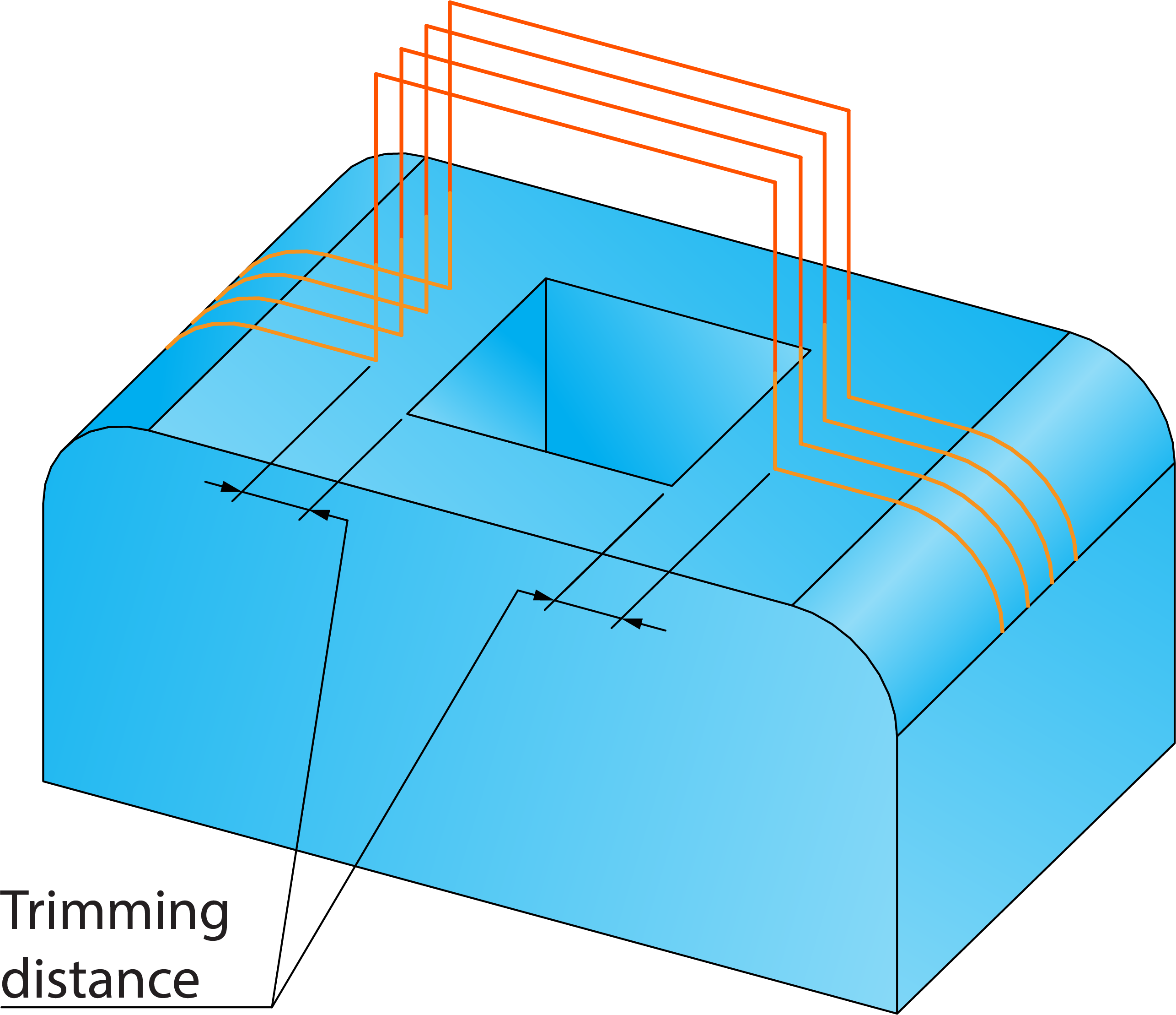
When the detected gaps are trimmed, the tool stops at the specified distance before the gap edge, performs linking in the gap area according to the parameters set in the Gaps along cut section of the Link page, and continues the machining of the current cut at the specified distance after the second edge of the gap. As a result, the tool path is trimmed over the gap area at both sides. |
 |
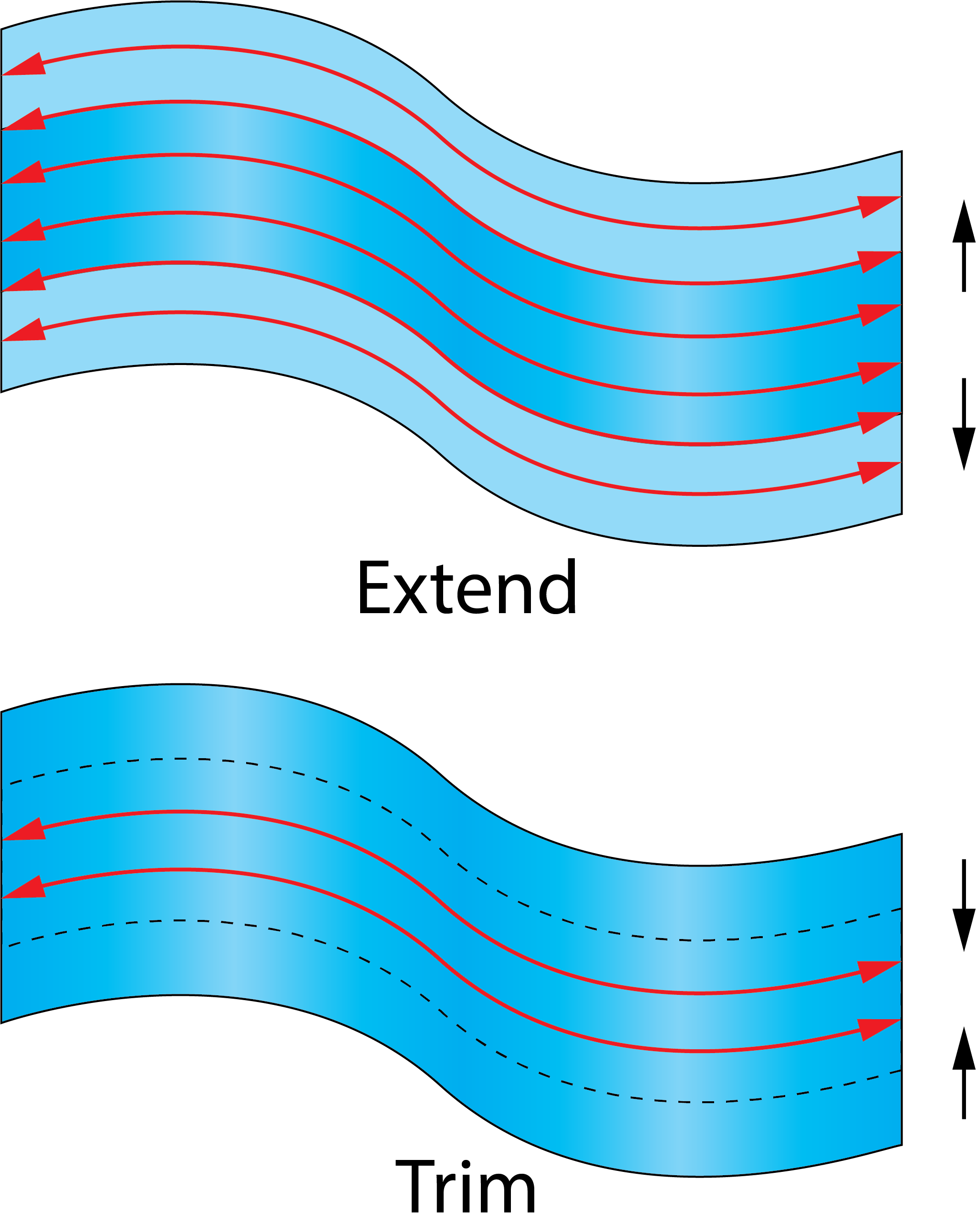
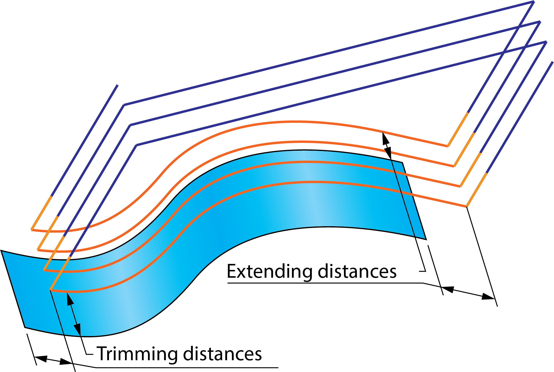
Side extensions
SolidCAM virtually extends or trims the drive surface across the cutting direction and generates the tool path for it. In the case of extending a tool path, cutting passes are added beyond the side of the surface to the specified distance. In the case of tool path trimming, cutting passes are eliminated before the surface boundary at the specified distance.
|
 |
For both extension types, the distances can be defined either by values or by percentage of the tool diameter. A positive value results in extending the passes; a negative value results in trimming the passes.
|
With the Zigzag option, the direction of the machining is changed for each cutting pass, so the start and the end of the passes are reversed for each pass. Therefore, to obtain the correct tool path, it is recommended to use the One way option. With this option, the start points of the passes are on one side of the drive surface and the end points are on the other side, providing you with the possibility of correct extending/trimming. |
|
The Extend/Trim option can be deactivated by clicking the corresponding check box. |