Constant Step over strategy
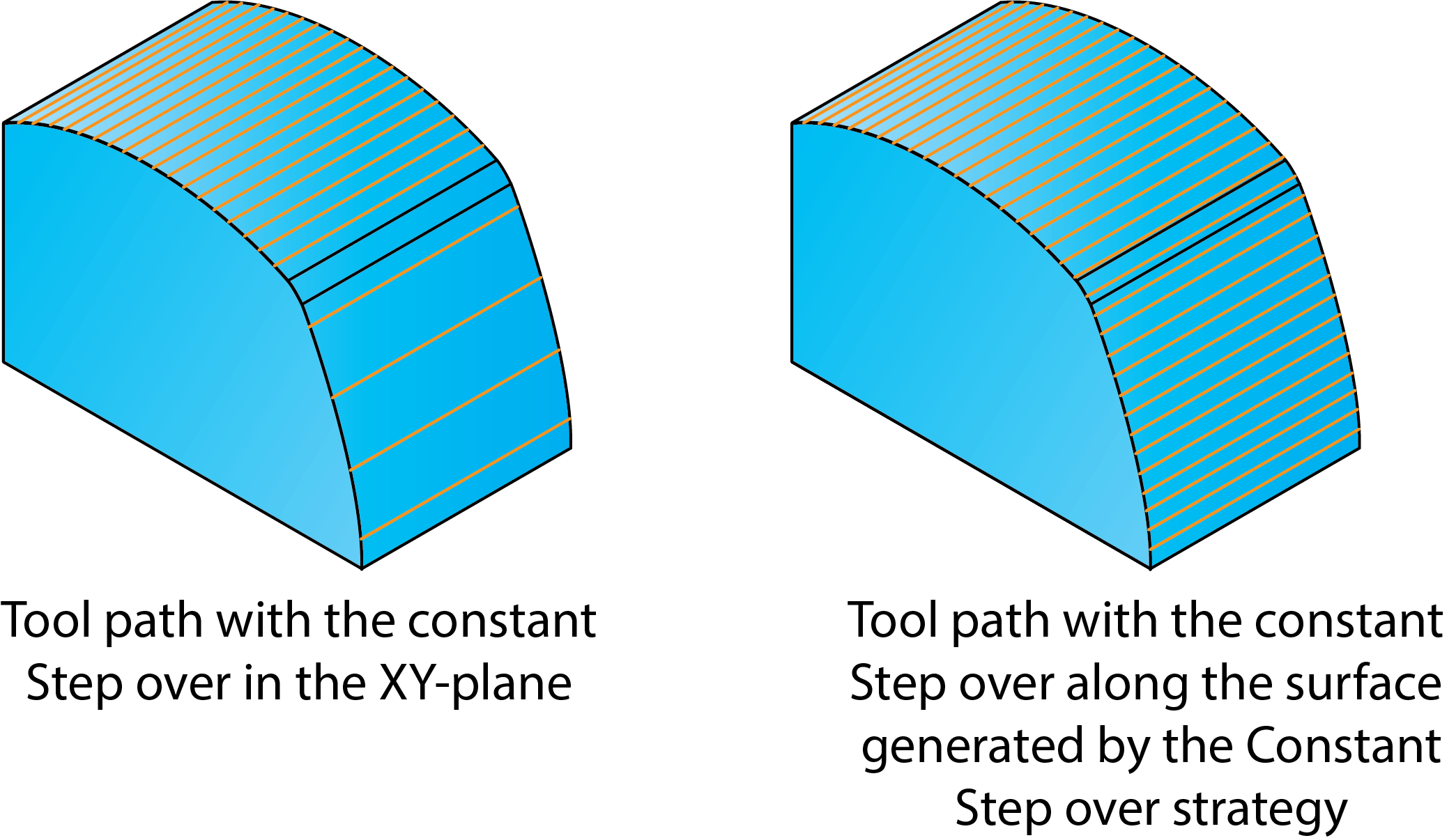
The 3D Projection Machining strategies generate a 2D tool path mesh, with a constant Step over in the plane parallel to the XY-plane of the current Coordinate System. This 2D tool path mesh is then projected on the 3D Model to get the 3D tool path. This method provides good results for prismatic parts machining but has a significant disadvantage for machining of curved surfaces because it does not take into account the surface curvature.
Constant Step over gives an excellent surface finish because the step over is constant along all surfaces irrespective of whether they are steep walls or shallow areas.
Operation type
SolidCAM provides five types of the Constant Step over strategy:
Pocket-auto boundaries
The appropriate geometry has to be defined for all of these options.
Tool path connections
Direction type
Zigzag
The tool mills one line of the offset pattern and then moves directly to the next line and so on. It mills forward and backward without leaving the material, thus constantly switching between climb and conventional milling.
One way
The tool mills one line of the linear pattern. At the end of the line, the tool rapidly moves (G0) to the safety distance and then to the start of the next cut line. The tool will always use climb or conventional milling.
Connection type
This option enables you to control the way the tool moves between two adjacent tool passes.
Stairs
The tool moves in two steps between two adjacent tool passes. If the next pass is lower than the present pass, the tool first moves away from the surface in the XY-direction and then downwards in Z. In case the next pass is higher than the present path, the tool first moves upwards in Z and then approaches the surface in the XY-direction.
Smooth
Between two adjacent tool passes, the tool moves on the surface of the model. The line connecting the two adjacent tool passes is projected on the model. When you use the Smooth option, the tool does not leave material when moving to the start point of the next pass.
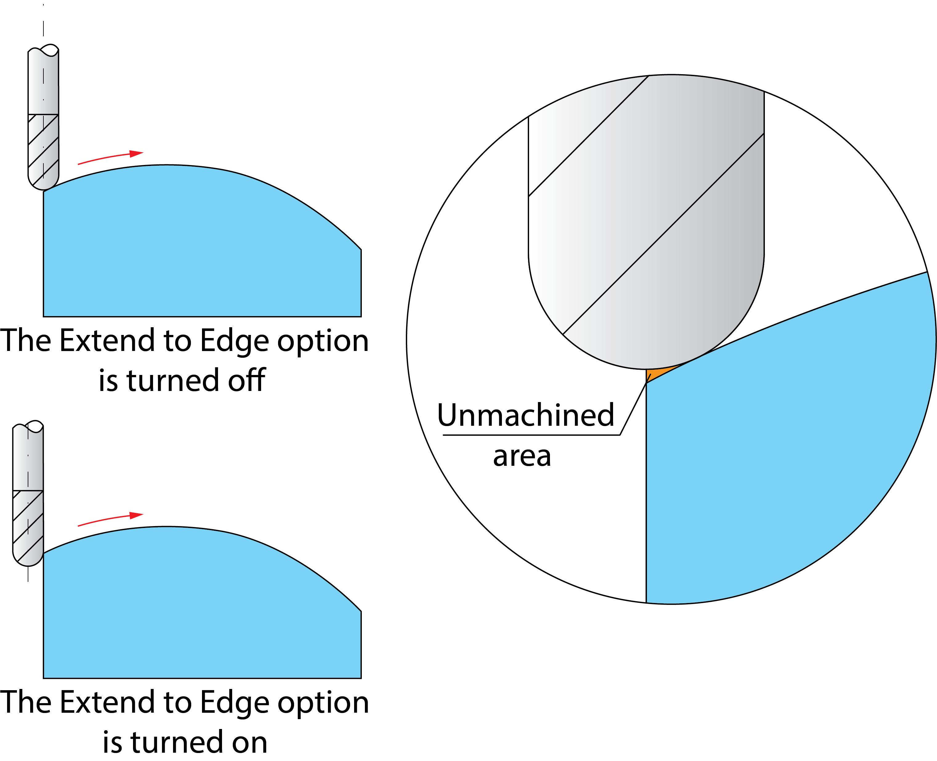
Extend to edge
When this check box is not selected, the tool path is generated from the position where the tool center is aligned with the end point of the face; this could leave an unmachined area. When this check box is selected, the tool path is extended till the tool is tangent to the face, at the start point of the face.
Related Topics