Defining the rotational axis
Defining the tilting table
At this stage, you can review the tilting table providing the B-axis rotation.
Click the A item in the CNC-Machine definition tree.
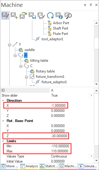
In the element properties table, the Direction and the Center point parameters determine the location and orientation of the rotational axis.
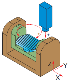
The tilting axis performs the rotation around the X-axis. Note that the positive tool movement around the rotational axis (positive direction of the B-axis) is performed by the negative rotation of the tilting table.
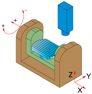
The positive direction of the rotational axis of the tilting table is defined by the right hand rule. Therefore the axis Direction parameters values must be the following: -1.00000 0.00000 0.00000.
The Center point parameters define the location of the axis relative to the CNC-Machine origin. In this case, the tilting axis is located 30 mm below the table. Therefore, the Center point values must be defined as follows: 0.00000 0.00000 -30.00000.
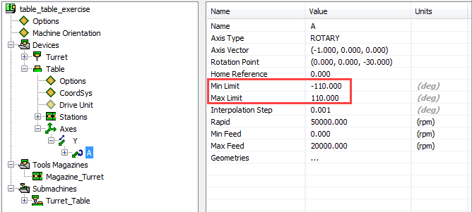
The minimum and maximum rotation angle limits are set in the Limits section: the Min Limit value is -110° and the Max Limit value is 110°.
Take a note that the same values must be set in the VMID file.
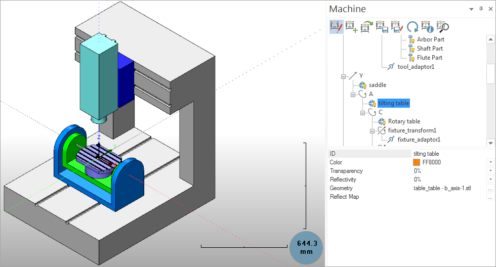
Now consider the geometry of the tilting table. In the CNC-Machine definition tree, click the tilting_table item. The tilting table is highlighted in the graphic area, and its parameters are displayed.
|
Use the sliders of the Axis Control tab to check the translational movements of the defined geometry along the axis. Double-click the right mouse button to highlight an object in the MachSim viewing area without opening the context menu. The object is also highlighted in the Machine Window (Tree view). |
Defining the rotary table
At this stage, you have to define the rotary table that provides the C-axis rotation.
Click the C item in the CNC-Machine definition tree.
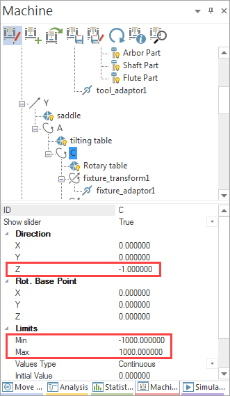
The rotary axis performs the rotation around the Z-axis. Note that the positive tool rotation around the rotational axis (positive direction of the C-axis) is performed by the negative rotation of the rotary table; the positive direction of the rotational axis of the rotary table is defined by the right hand rule. Therefore the axis Direction parameters values are the following: 0.00000 0.00000 -1.00000.
The Center point parameters define the location of the axis relative to the CNC-Machine origin. The rotational B-axis passes through the CNC-Machine origin. Therefore, the Center point has to be defined with the following values: 0.00000 0.00000 0.00000.
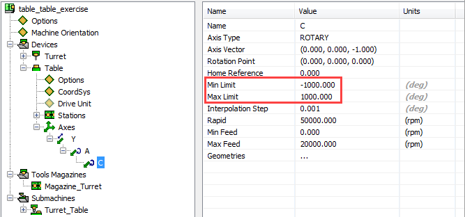
The minimum and maximum rotation angle limits are set in the Limits section: the Min Limit value is -1000° and the Max Limit value is 1000°.
Take a note that the same values must be set in the VMID file.
The geometry of the rotary table is defined in the Rotary table item.
|
Use the sliders of the Axis Control tab to check the translational movements of the defined geometry along the axis. |
The Rotary table item is followed by a series of transforms: fixture_transform1, fixture_adaptor1, workpiece_transform1, wcs1, and workpiece_adaptor1. These items are reserved for coordinate system transformations performed as you load an actual part and add more data on fixture, workpiece and so on.
Related Topics