View Toolbar
The view tab provides you with the option of choosing which docking panes you want to display in the simulation area.
Viewports
The Viewports section enables you to split the machine simulation area different views. For each of these views independent and different orientations can be displayed.
|
Maximize enables you to visualize the simulation view better when you click on other viewports and then wish to enhance a specific view to see the simulation accurately.
|
||
|
4 Views enables you to split the machine simulation view in four different orientations. Clicking on any one of them, and then clicking Maximize displays only the selected orientation in the simulation pane. | ||
|
3 Views enables you to split the machine simulation view in three different orientations. Clicking on any one of them, and then clicking Maximize displays only the selected orientation in the simulation pane. | ||
|
2 Rows enables you to split the machine simulation view in two rows. Clicking on any one of them, and then clicking Maximize displays only the selected orientation in the simulation pane. | ||
|
2 Columns enables you to split the machine simulation view in two columns. Clicking on any one of them, and then clicking Maximize displays only the selected orientation in the simulation pane. | ||
|
|||
|
After splitting the screen, the sizes of the viewports can be adjusted. Reset Views Layout enables you to reset the layout to defaults. | ||
|
For each viewport: 4 Views, 3 Views, 2 Rows, and 2 Columns there is a preimposed (default) orientation. If these are modified, Reset Views Content enables you to return to the default orientation. | ||
Screen Objects
The Screen Objects section enables you to measure the part in the simulation area.
|
Measure Grid enables you to easily measure objects on screen. When you click Measure Grid, a grid is displayed on the entire view area. |
Export & Capture
The Export & Capture section enables you to capture the machine simulation in the simulation view area. You can create an image or capture videos using the available options.
|
Capture Graphics Area enables you to save the picture of the graphics area as a .bmp file. |
|
Start Capture Video enables
you to save the video of the graphics area as a .mp4 file. Once
the desired video is captured, click Stop
Capture Video |


|
The output of these options is stored on you computer in a folder named machsim at C:\Users\XXX\Pictures.
|
Move List
This window displays the lines of the GCode as the operation is running on; the active GCode line is highlighted. SolidCAM enables you to display coordinates relative to the CAM-Part coordinate system or to the CNC-Machine origin, depending on the Machine simulation settings.
The slider to the right enables you to navigate through the GCode. If you start tool path at any operation, you can see the last axes values of the previous operations. This option is enabled only if the Show Last Axes values check box is selected in SolidCAM Settings. You can also see the machine position at the start and end of the program if Show Start/End Program check box is selected in SolidCAM Settings. The VMID controls the home reference & whether to move axes to home reference at start only, end only or both.
The moves that appear in Move List, can now be colored based on the Toolpath Analysis check box selected.
The option can be activated by right-clicking on the Move List docking pane. On the context menu that appears, click Settings.
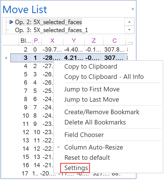
The Move List Settings dialog box is displayed.
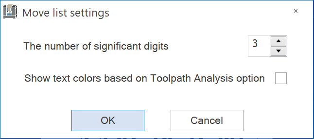
Select the option of Show text colors based on Toolpath Analysis option.
Analysis (Toolpath)
This window contains color representation of various elements of the simulation to facilitate the visualization. Choose an element from the list to display its analysis in colors.
You can change the color for each item by double-clicking on the corresponding rectangle and choose the desired color from the displayed Windows-style Color dialog box.
Toolbar Buttons
![]() Refresh enables you
to update the simulation when changes have been made in the analysis settings.
Refresh enables you
to update the simulation when changes have been made in the analysis settings.
![]() Add
enables you to add values into the table.
Add
enables you to add values into the table.
![]() Remove enables you
to remove selected values from the table.
Remove enables you
to remove selected values from the table.
![]() Adjust
enables you to set limitations for specific parameters to display the
tool path in different colors according to the defined settings.
Adjust
enables you to set limitations for specific parameters to display the
tool path in different colors according to the defined settings.
![]() Auto
adjust When you click this
button, the system automatically sets the parameter ranges for the defined
settings.
Auto
adjust When you click this
button, the system automatically sets the parameter ranges for the defined
settings.
Parameters
The Analysis window also enables you to perform quality analysis and checking the excess and overcut material. The parameters available are the same as in the Analysis (Toolpath) window except the following two parameters:
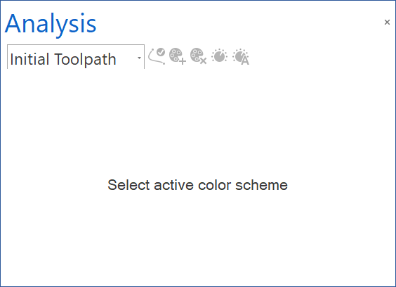
| Initial
Toolpath
|
|
When you choose this element
from the list, the tool path is displayed with the default colors
available in SolidCAM.
|
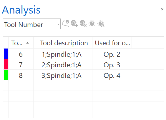
| Tool
Number
|
|
When you choose this element from the list, the table displays the tool path color scheme according to the tools used in part operations. The tools are numbered in the corresponding column and represented by rectangles of different colors in the left most column.
|
| Operation
Number
|
|
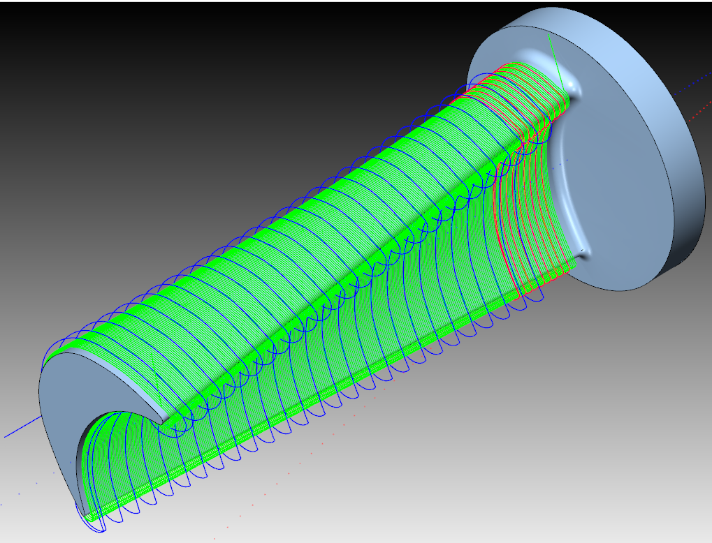
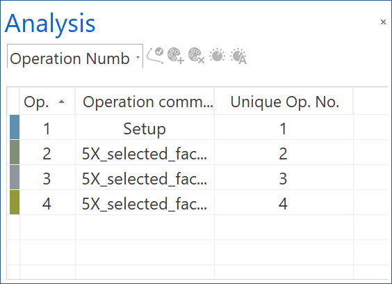
When you choose this element from the list, the table displays the tool path color scheme according to the part operations. The operations are numbered in the corresponding column and represented by rectangles of different colors in the left most column. |
| Operation
Highlight
|
|
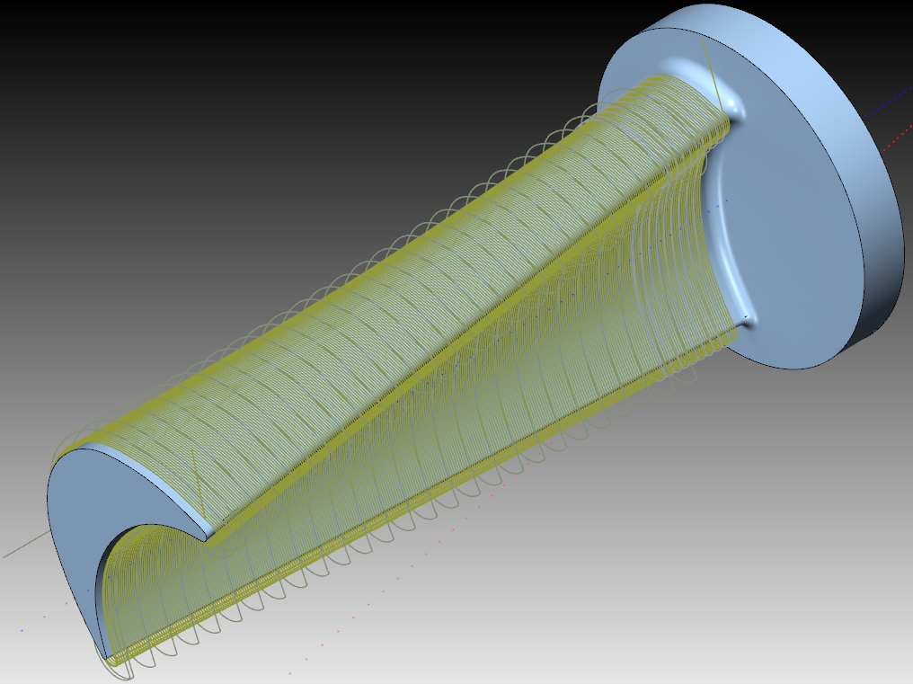
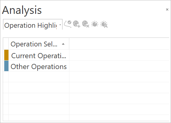
When you choose this element from the list, you can highlight the current operation with a separate color from the other operations. This option allows you to change the two colors from the interface. The colors can be customized at integration level. The defaults can be restored by pressing the Auto Adjust button. |
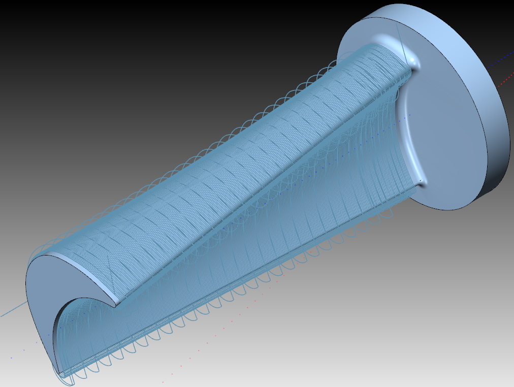
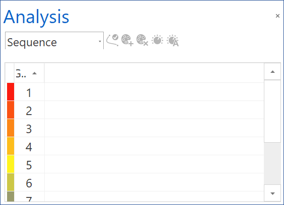
| Sequence
|
|
When you choose this element from the list, the tool path is represented in a gradient color scale according to the progress of machining. This scale enables you to easily identify the start point and the end point of the machining, the cutting method (e.g. Zigzag or One way), the cut order(e.g. from outside to inside), and other machining parameters. |
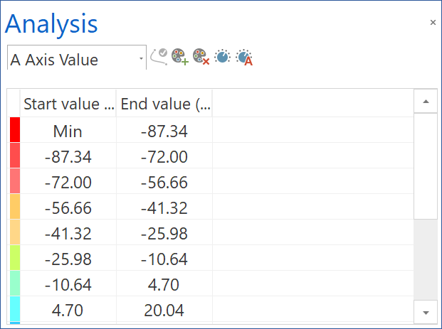
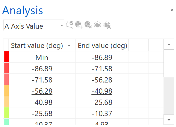
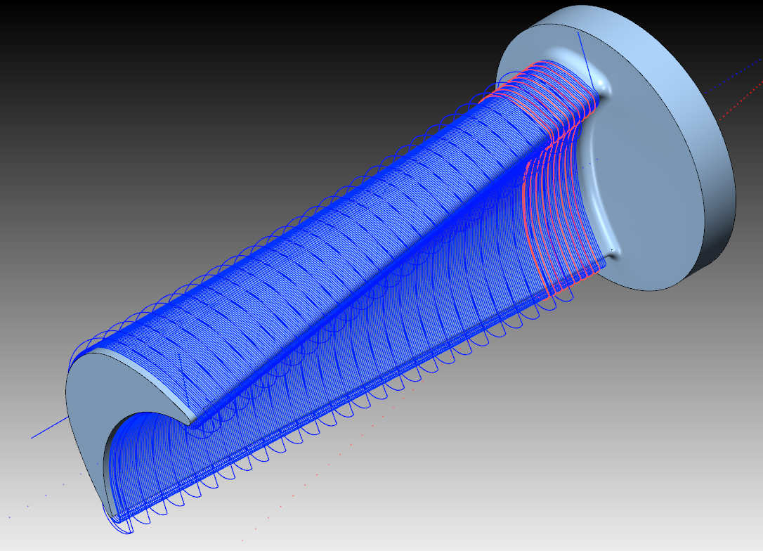
| A
Axis Value / C Axis value
|
|
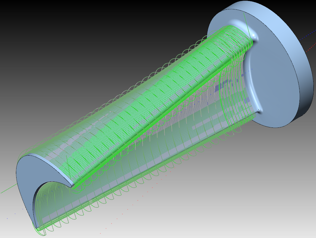
When
you choose this element from the list, the tool path is represented
in a gradient color scale according to tilting angles of the machine
rotation axis.
This scale enables you to identify the rotation
axis angle range used in the operation, the rotation angle used
for machining of specific areas, and limit overruns that occur
during the simulation.
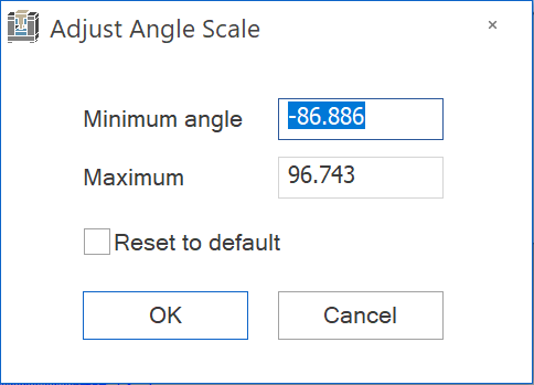
The angle range values are displayed in the corresponding columns of the table. You can define a specific angle range to view the tool path in the corresponding colors. Click Adjust
Click Refresh |
| A
Axis Value change / C Axis value change
|
|
When you choose this element from the list, the tool path is represented in different colors based on the change in degrees of a rotation axis value. This option indicates angle changes in the tool path moves. |
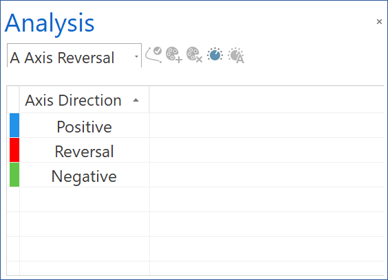
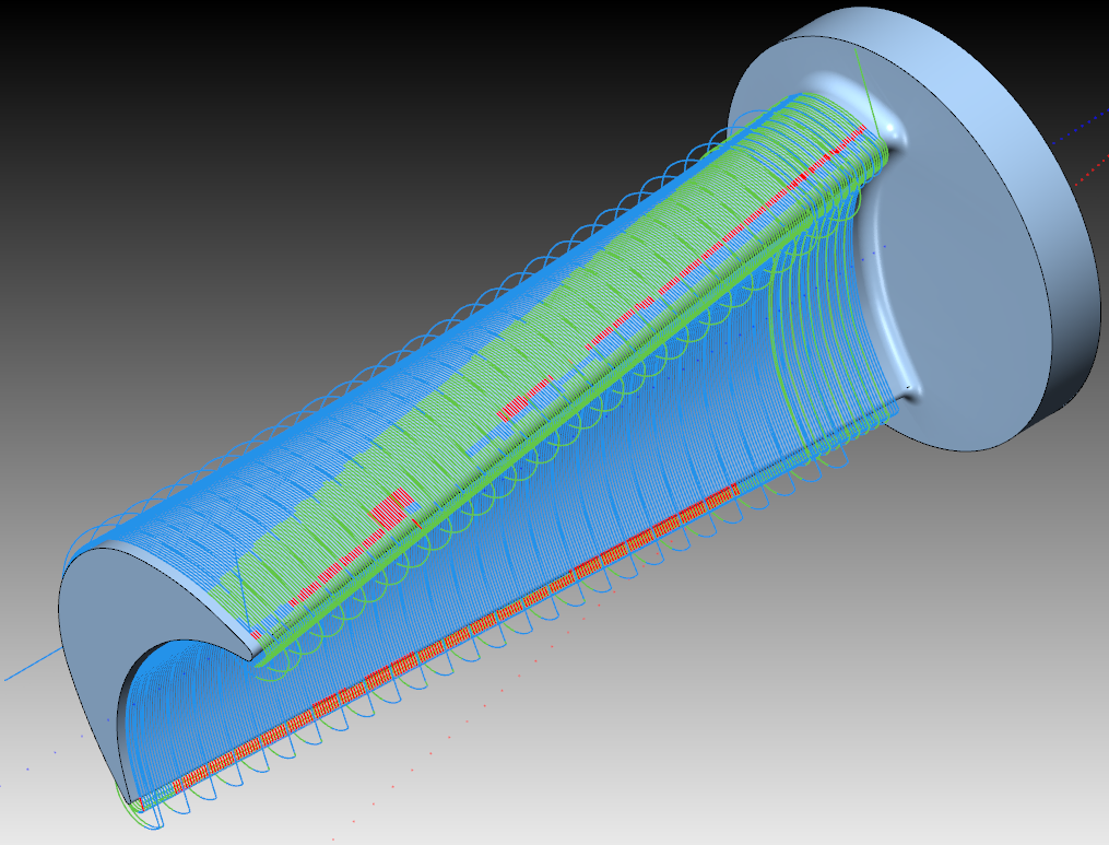
| A
Axis Reversal / C Axis Reversal
|
|
When you choose this element from the list, the tool path is represented in colors according to change of direction of the machine rotation axes. These colors enable you to identify the areas where possible contouring errors have negative influence on the machining result (surface quality). Every time when a rotation axis changes its direction, the tool path segment changes its color. |
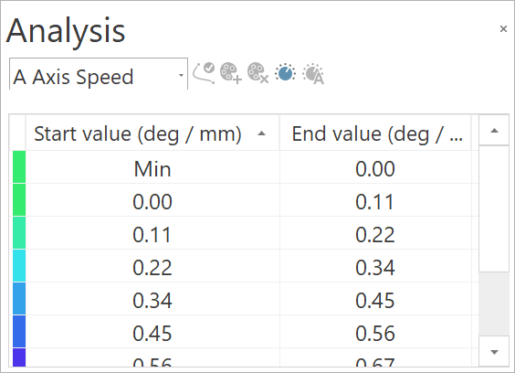
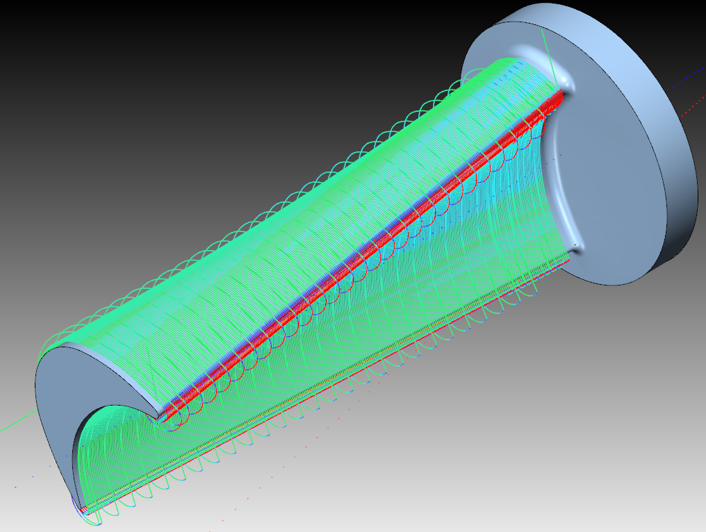
| A
Axis Speed / C Axis Speed
|
|
When you choose this element from the list, the tool path is represented in a gradient color scale according to change of tilting angles of the machine rotation axis. This scale enables you to identify the rotation speed range used in the operation, the rotation speed used for machining of specific areas and determine the areas where machine speed limits are reached. You can define a specific angle range to view the tool path
in the corresponding colors by clicking Adjust
Click Refresh |
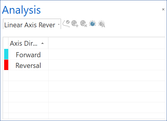
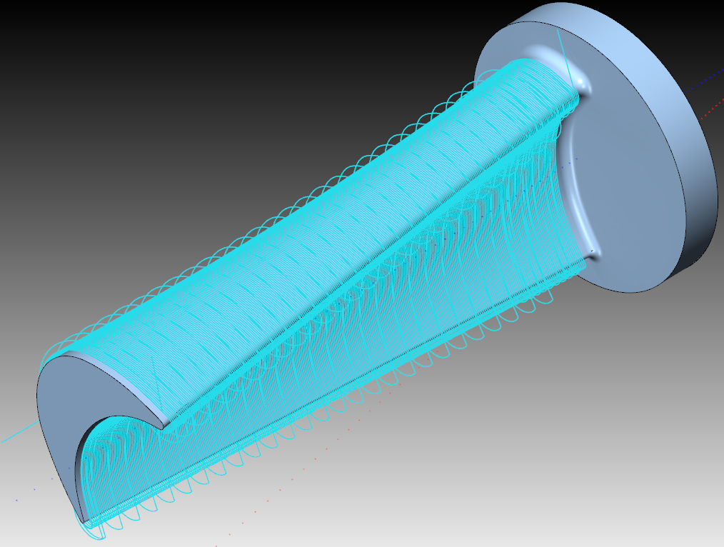
| Linear
Axis Reversal
|
|
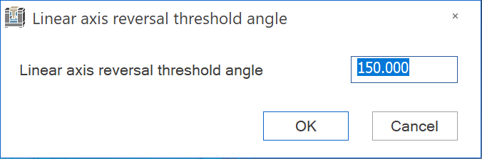
When you choose this element from the list, the tool path is represented in colors according to change of direction of the machine linear axes. Every time when a linear axis changes its direction, the tool path segment changes its color. You can define a threshold angle value for the axis reversal to view the tool path in the corresponding colors by clicking on the Adjust button and entering the values into the Linear axis reversal threshold angle dialog box.
Click Refresh
|
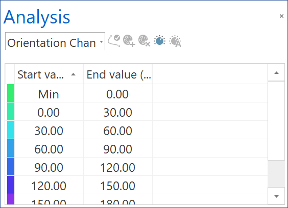
| Orientation
Change
|
|
When you choose this element from the list, the tool path is represented in a gradient color scale according to change of orientation of the machine rotation axes. This scale enables you to identify the rotation speed range used in the operation, the rotation speed used for machining of specific areas and determine the areas where machine speed limits are reached. |
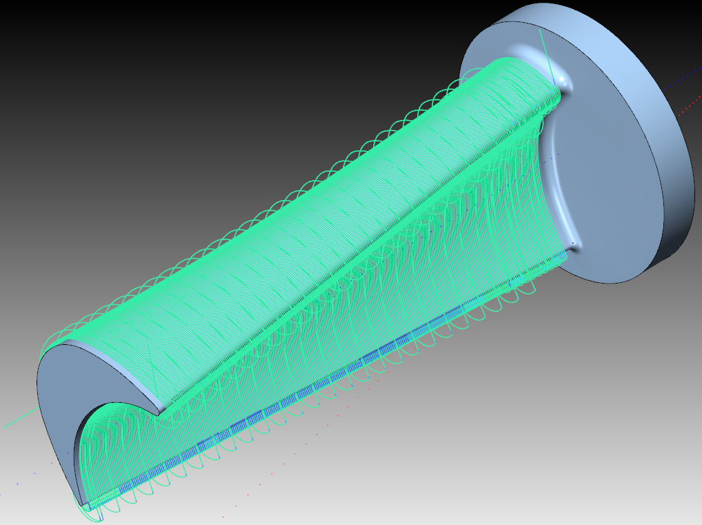
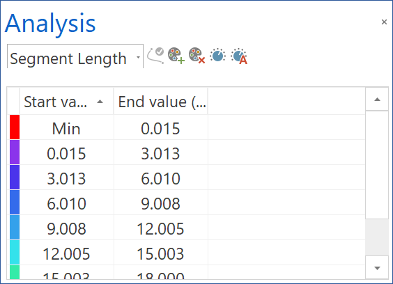
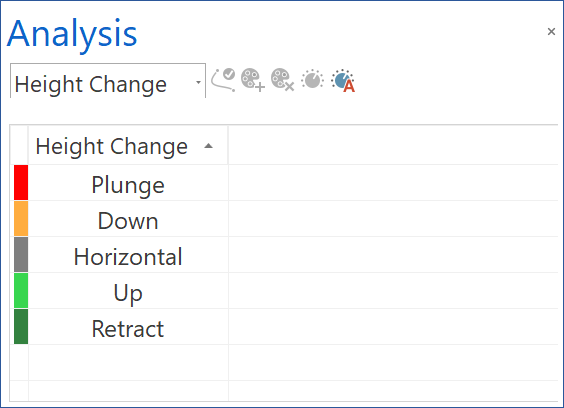
| Segment
Length
|
|
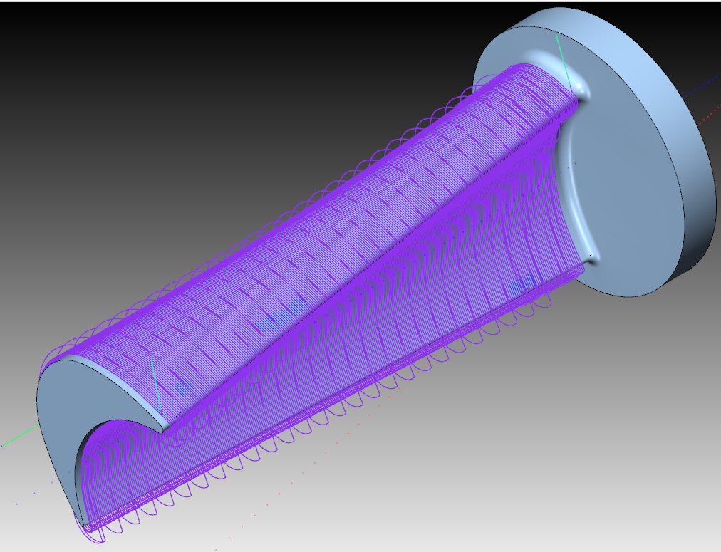
When you choose this element from the list, the tool path is represented in colors according to the length of its segments. These colors enable you to identify the areas where you have long linear motions, usually in roughing tool path or where the segments become very short, e.g. for finishing. You can define a specific segment length range to view the tool path in the corresponding colors. Click the Adjust button in the toolbar to the right from the options list. The Adjust Segment Length dialog box is displayed. This dialog box enables you to enter the minimal and maximal values for the length range and return to default values, if necessary.
Click Refresh
|
| Collisions
& Proximity
|
|
When you choose this element from the list, the tool path is represented in colors according to the collision status. • Segments with collisions are marked red. • Collision and proximity alert free segments are marked green. • Segments in proximity area are marked yellow. • Segments that were not checked yet are marked gray. |
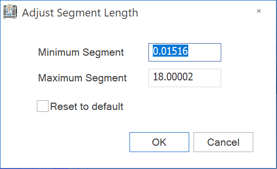
| Feed
rate
|
|
When you choose this element from the list, the tool path is represented in colors according to the feed rate. • Segments with machining feed rate are marked blue. • Segments with rapid feed rate are marked yellow. |
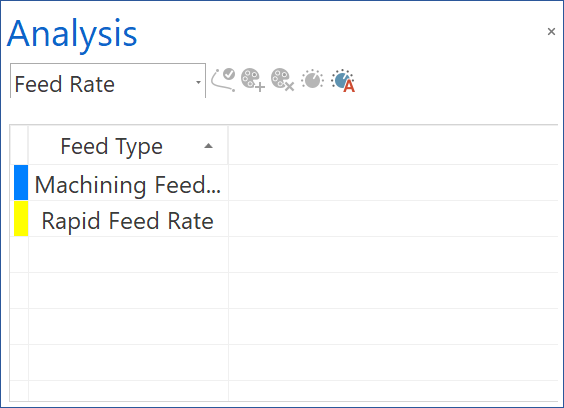
| Height
Change
|
|
When you choose this element from the list, the tool path is represented in colors according to the tool orientation relative to the tool path. • Segments where the plunging is performed in the tool axis direction are marked red. • Segments with the lag angle tool orientation are marked orange. • Segments with the normal tool orientation are marked gray. • Segments with the lead angle tool orientation are marked light green. • Segments where the tool retracts along the tool axis are marked green. |
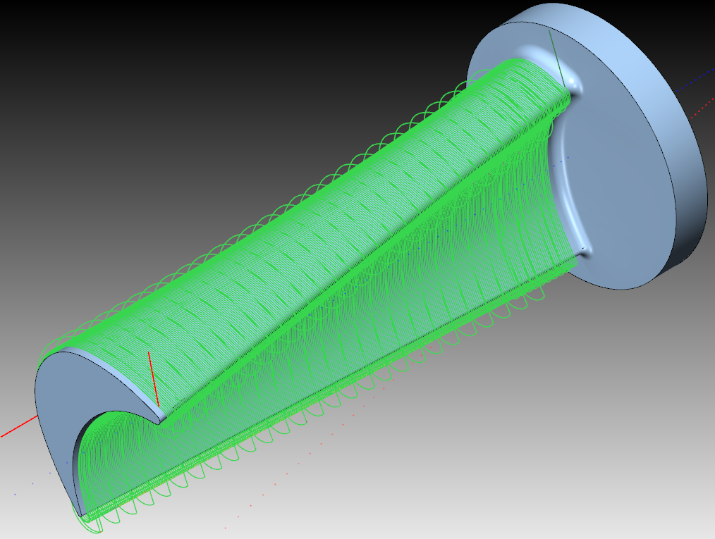
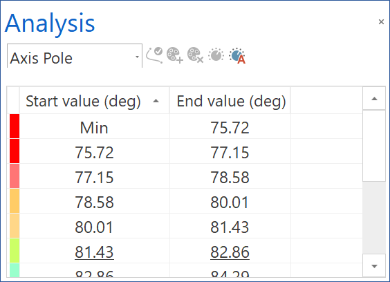
| Axis
Pole
|
|
When you choose this element from the list, the tool path is represented in a gradient color scale which enables you to determine whether the two rotational axes are collinear. The more the axes get collinear, the tool path turns more red. This option is useful for simulation of impeller parts machining. You can define a specific tool axis angle range to view the tool path in the corresponding colors. Click the Adjust button in the toolbar to the right from the options list. The Adjust Axis Pole dialog box is displayed. This dialog box enables you to enter the minimal and maximal values for the angle range and return to default values, if necessary. Click the Refresh button in order for the change to take effect. |
| A
+ C Axis Speed
|
|
When you choose this element from the list, the tool path is represented in a gradient color scale according to the change of tilting angle of rotational axes. This scale enables you to identify the rotation speed range used in the operation, the rotation speed used for machining of specific areas and determine the areas where machine speed limits are reached. |
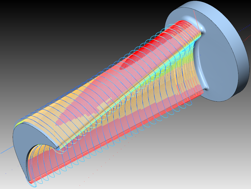
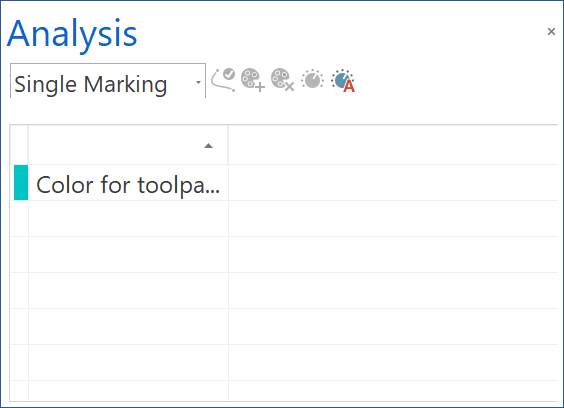
| Single
Marking
|
|
When you choose this element from the list, you can apply a single color of your choice to the tool path. |


• Deviation
When you choose this element from the list, you can make a comparison between machine stock and the CAM-part.
• Tool Path Length
The tool path length indicates the length of the tool path segments. It is useful to identify if the tool path points are equally distributed on the work piece to ensure stability.
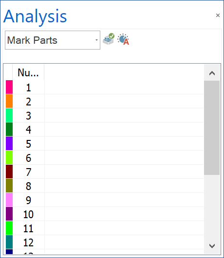
• Mark Parts
When you choose this element from the list, the main part is separated into smaller parts of different colors. It is useful to identify the parts by color after machining.
• Gouge and Excess
When you choose this element from the list, the gouge information is represented.
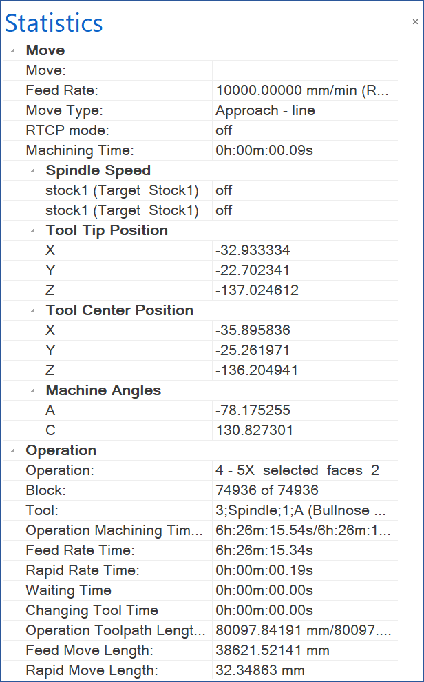
Statistics
The statistics show useful information about the machining process. It is grouped into three main sections:
Move This shows information about the current move. Operation This shows information about the current operation. Sequence This shows information about all operation together. |
 |
Machine
This window displays the CNC-Machine definition tree and enables you to define the CNC-Machine and manage the CNC machine components displayed in the graphic area. When you click on an axis, the arrow in the main window shows the direction of movement of the selected axis.
The buttons in the tab toolbar enable you to manage existing machine definitions and add new ones.
|
Edit Machine allows editing the current machine definition. This option is enabled only in special cases. |
|
New Machine enables you to create a new machine definition. |
|
Open Machine File enables you to load a different existing machine. |
|
Save Machine enables you to save the edited machine definition. |
|
Save Machine As enables you to save the edited machine definition under a different name and/or in a different folder. |
|
Show information toggles the display of the information about the listed machine components. |
|
Machine Kinematic Search allows
you to search the axis or elements of the machine. The up and
down arrows enable you to navigate through the findings made during
the search through the Machine Kinematic elements. When you click
the up or down arrow, the selection bar from kinematic tree jumps
to the next up or down element.
 |
The CNC-Machine definition tree displays all components of the CNC-Machine used for the machining of the current CAM-part. The tree displays all the structure of the CNC-Machine and the relation between all the CNC-Machine components.
SolidCAM enables you to manage the CNC-Machine components using the right-click menu available on each component.
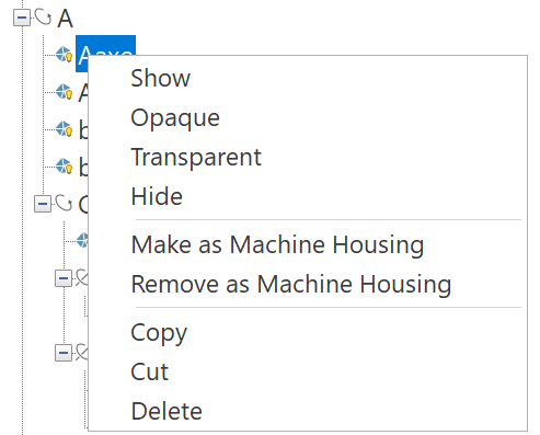
• Show/Hide
This option enables you to show/hide the chosen component of the CNC-Machine.
• Transparent/Opaque
This option enables you to control the transparency of the chosen component of the CNC-Machine.
• Make/Remove as Machine Housing
This option enables you to toggle the display of the machine housing in the graphic area of the simulation.
• Copy/Cut/Delete
These options enable you to copy, cut or delete selected elements.
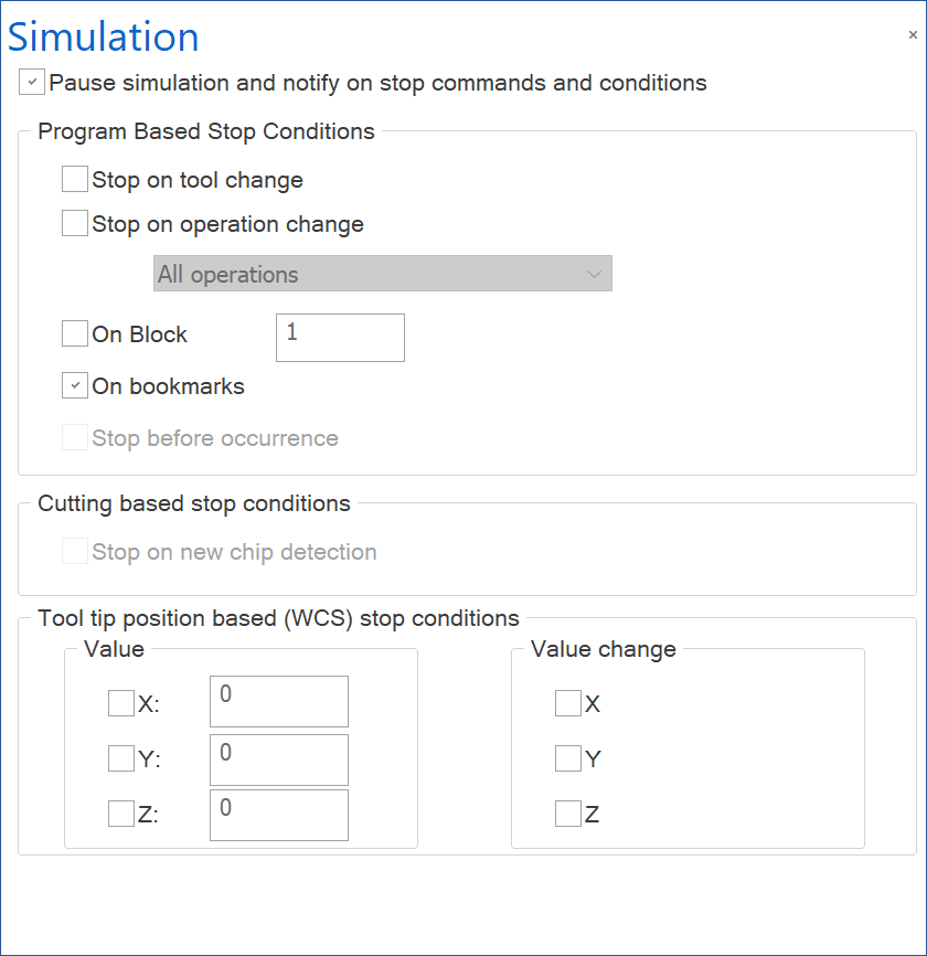
Simulation
This window enables you to set the stop conditions. The stop conditions can be used to set program based stop conditions, cutting based stop conditions, or tool tip based stop conditions. |
 |
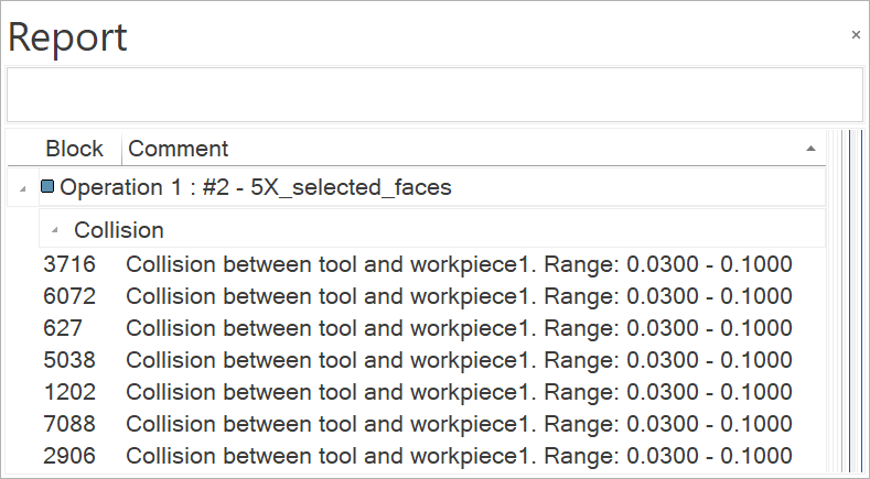
Report
This window lists the operations with tools used and all events that happen during simulation. The items in the report are listed in a tree format structure as operations followed by the tool number and the tool definition. The report items display a warning message if the chips from the part were removed during machine simulation. |
 |
Progress
The Progress bar shows the advance of the simulation process. It consists of a slider that moves as the simulation is running on and a colored stripe that represents different tools by different colors. The colors of the tools are also displayed in the Report tab.

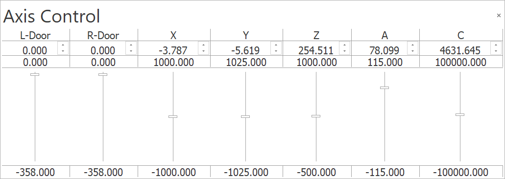
Axis Control
This window enables you to control the tool location manually using the axis sliders. It displays the current coordinates of the CNC-Machine. Each axis has a control slider that enables you to perform manual movements within the specified limits.
|
|
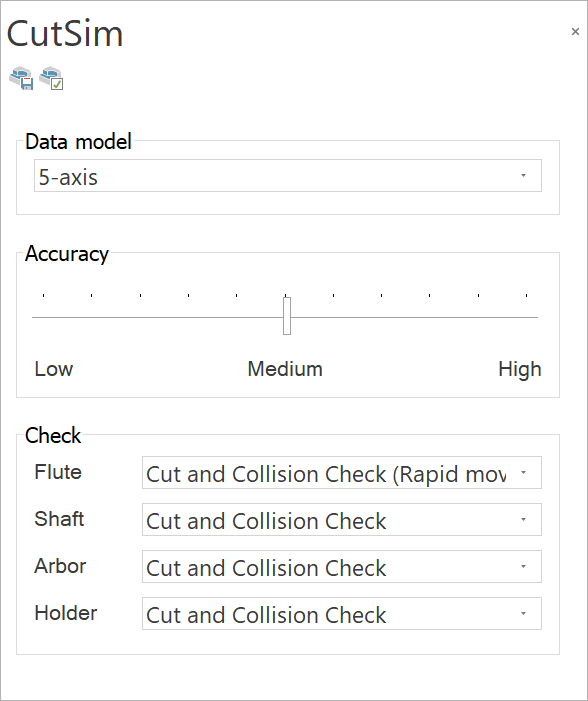
CutSim
This window provides the parameters for material removal.
|
|
Analysis
When you choose this element from the list, the main part is separated into smaller parts of different colors. It is useful to identify the parts by color after machining.
|
|
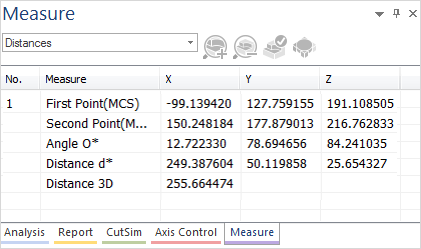
Measure
This window provides different features to measure the stock. You can evaluate the distance between points from any machine geometry. For points, the WCS (Workpiece Coordinate System) is displayed. For distances, MCS (Machine Coordinate System) is displayed. |
|
Reset
![]() This
option enables you to reset the windows in the View tab.
This
option enables you to reset the windows in the View tab.