Tool axis control
The Tool axis control page enables you to define the orientation of the tool axis.
Output format - This section enables you to choose the Output format of the current operation. The following options are available:
3 Axis
This option is suitable to be used with 3-Axis Machines.
A single tool axis direction must be specified. When the tool cannot reach a specific area, the tool path is trimmed resulting in non-machined edges.
The currently available Ball mill cutters (Ball Nose Mill, Taper Ball Nose and Lollipop mill) that have a conical shaft have limitations when tool axis is 3-Axis and edges to be machined are vertical. This results in a trimmed tool path and is created only on the edges of shallow areas.
4 Axis
Use this option when you have a 4-Axis Machine with no Y-axis offset.
This option creates 4-Axis rotary tool paths. The tool axis is orthogonal to the selected rotary axis and always points directly towards the rotary axis.
Tool Axis Direction - Refer Rotary axis section.
4+1 Axis (Autotilt)
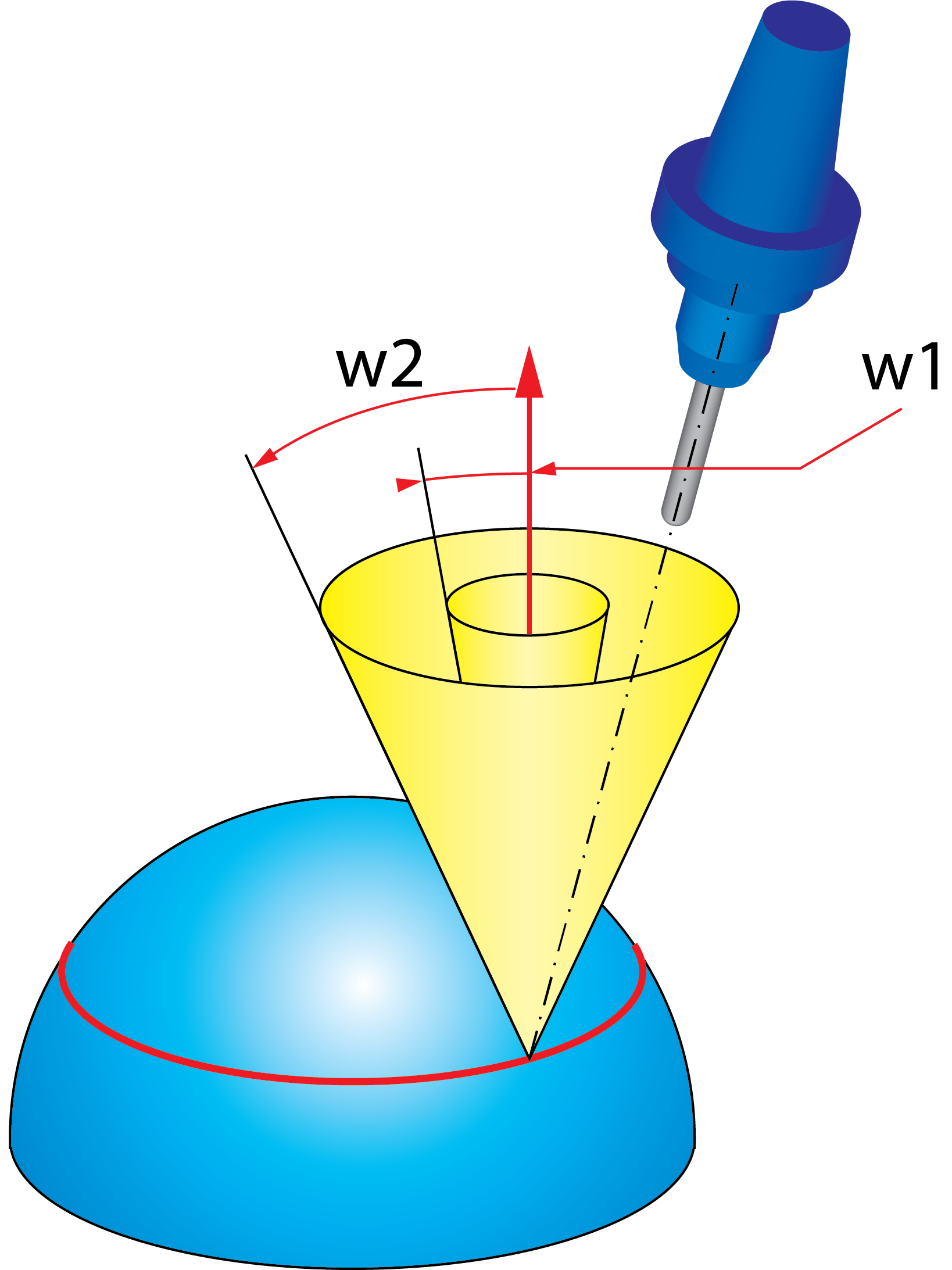
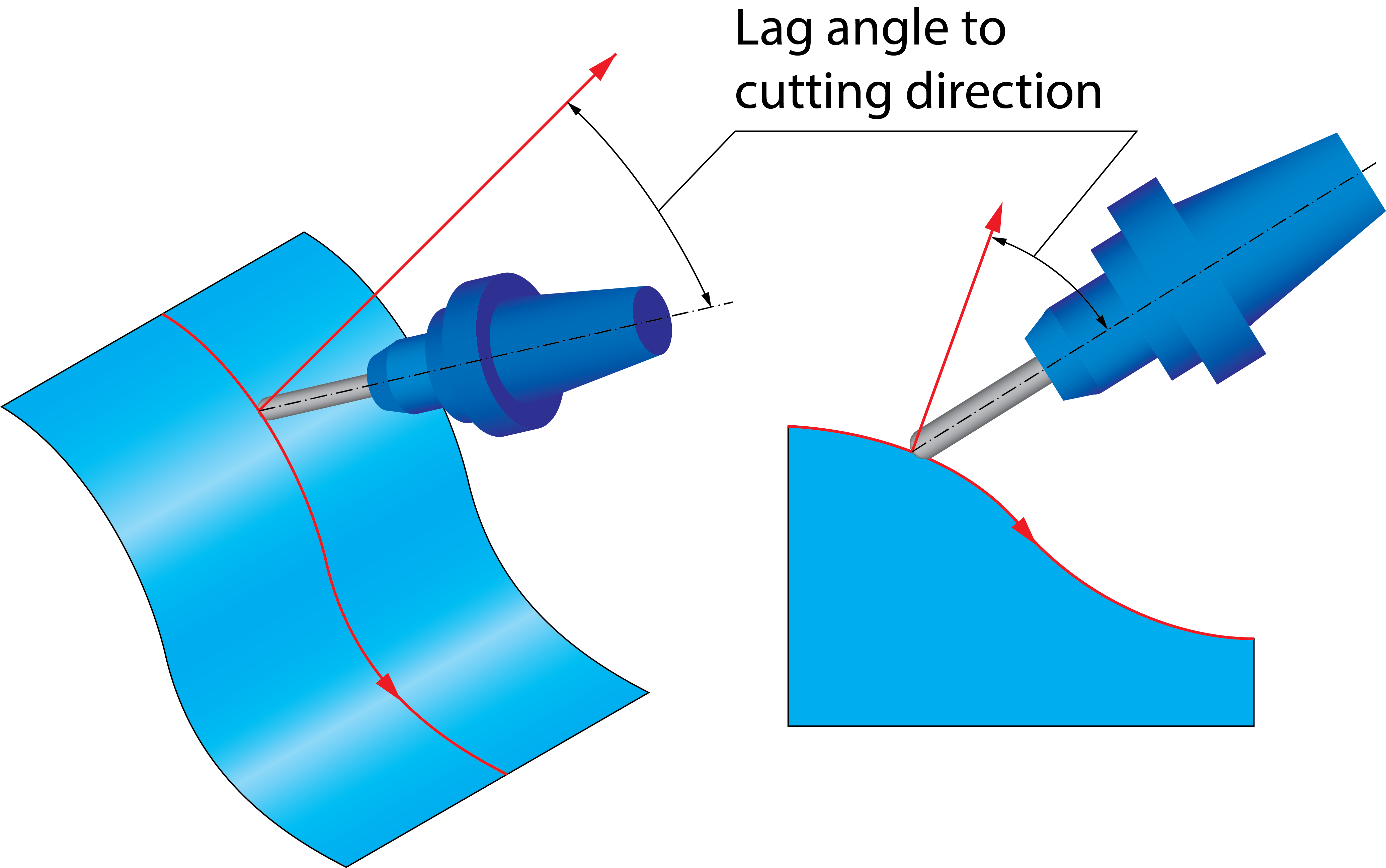
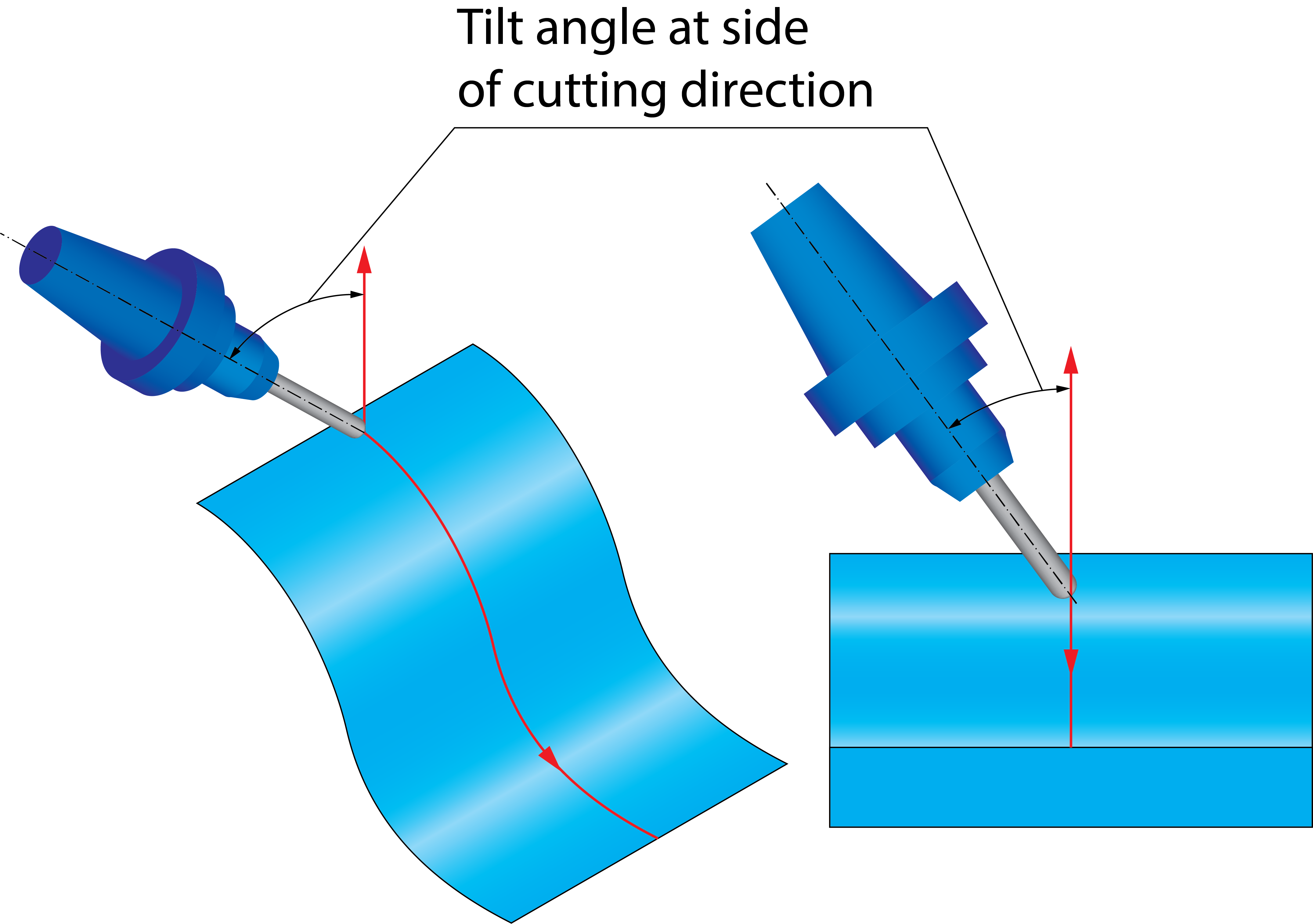
This option creates 4-Axis simultaneous output and keeps only the (side) tilt angle constant. The system tries to keep the tool orthogonal to the edge.
The user must specify a rotation axis as reference, and a fixed angle.
For example, if you have a cylindrical part aligned in the +Z direction and mounted on a rotary C table, you can lock the B-axis or A-axis with the fixed angle. This allows the rotary table to rotate back and forth which enables the tool to be orthogonal to the edge while A and B remain fixed.
Tool Axis Direction - Refer Rotary axis section.
Point tool to rotary axis
This option locks the tool axis to the rotation axis, preventing the tool from tilting in the lead/lag direction.
Locked at angle
4-Axis Machines sometimes have a fixed tilted head, for example a 45-degree head. In this case, the spindle direction is tilted 45 degrees towards the rotary axis vector, which means the locked axis value must be set to 45 degrees. A value of "+45" means the vector from the tool tip towards the spindle direction and the rotary axis vector [e.g. the X-axis vector which is (1,0,0) ] have a +45 degree angle to each other.
|
To reduce rotary axis motion, you can use a 5-Axis machine and set the tool path output to 4-Axis with a fixed 5th angle. This fixes one of the rotary axes for the whole tool path. |
5 Axis (Minimal Tilting)
This option is available only on a 5-Axis Machine. When this option is selected, SolidCAM keeps the tool axis fixed as much as possible.
Normal to contour - After initial tilting, SolidCAM keeps the tool orthogonal to the edge and the tool axis in the bi vector between the two surfaces of the edge. Selecting the Tilt range check box, enables the Third axis button. Selecting this button opens the Third axis dialog box which works in the same manner as the 4th axis dialog box.
Fixed to main axis - When this option is selected, it keeps the tool axis at a fixed angle to an axis, but with the possibility to tilt away if required. Third Axis button is enabled when Fixed to main is selected in Tool Axis direction. Selecting this button opens the Third axis dialog box which works in the same manner as the 4th axis dialog box.
5 Axis
This option is available only on a 5-Axis Machine. The Tool axis section for 5 Axis is similar to 5 Axis (Minimal Tilting) except that the Axis button is enabled instead of 3 Axis button.
|
Collision checking can change the tilting to 5-Axis Simultaneous tilting to avoid collisions if required. |
Rotary Axis
Click Rotary axis to display the 4th Axis dialog box.
This dialog box enables you to choose the rotary axis
(X-, Y-, Z-axis of the Coordinate System or another User-defined axis).
The Direction dialog box (available with ![]() )
enables you to define the direction vector by its coordinates (dX, dY
and dZ parameters). Using
)
enables you to define the direction vector by its coordinates (dX, dY
and dZ parameters). Using ![]() ,
SolidCAM enables you to pick the start and end
points of the vector directly on the solid model.
,
SolidCAM enables you to pick the start and end
points of the vector directly on the solid model.
Rotary axis around
This parameter defines the rotary axis. SolidCAM enables you to choose an axis of the Coordinate System (X, Y, Z -axis of the Coordinate System or another User-defined axis).
Rotary axis base point
With this option, SolidCAM enables you to define the position of the rotary axis directly on the solid model using Select point button.
Interpolation
Maximum angle step
This option sets the maximum allowed angle change between two consecutive tool path positions. The calculation engine outputs 5-Axis tool path data that contains the tool tip position and the direction vector of the tool. The direction vectors must not have an angle change more than the value specified here.
This option also defines the resolution of the maps used for collision checking. This means that collisions are checked every 3 degrees (angle change of the tool axis). A 3 degree step angle is usually enough, depending on the model geometry and the tool geometry. If there are sections along the contour where the tool is very close to the geometry, a 3 degree step might be too large to find a solution and a finer resolution should be used (2 degrees, 1 degree or even smaller)
|
This parameter had a big impact on the computing speed, and can cause a failure if there are sections where the solution exists only for a couple of degrees in the orientation of the tool. |