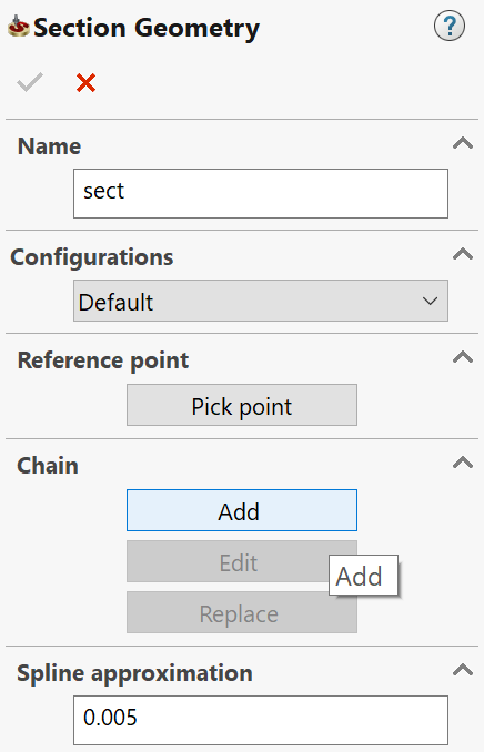
Defining the Section geometry
In Translated Surface and Slot operations, you must select a Section geometry. These 2.5D operations can be defined using 2D geometries only. Use section geometries to define depth profiles for Translated Surface and Slot operations.
Adding a Section geometry
2. The Chain Options dialog box is displayed.
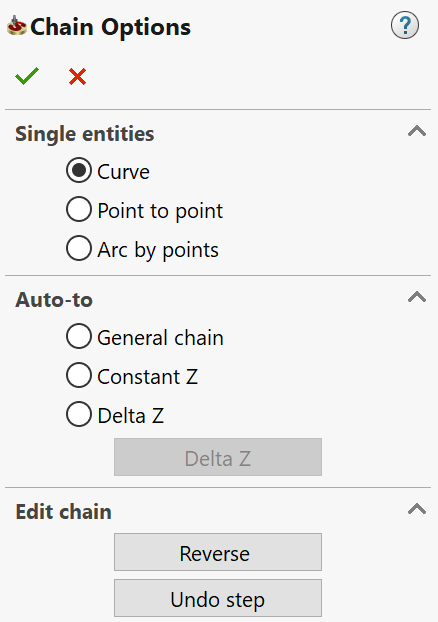
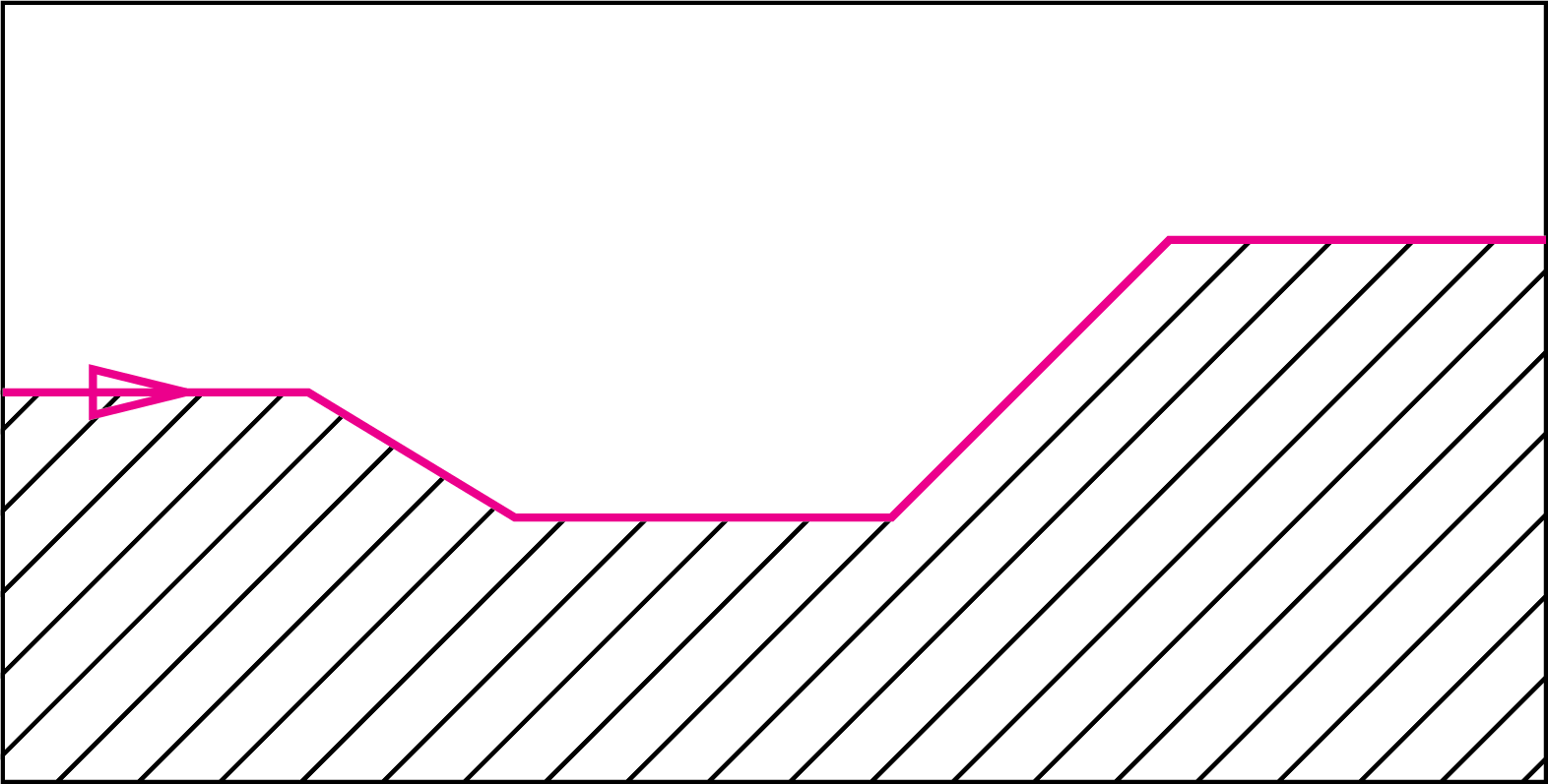
- Pick on the edges or lines that make up your section
and then confirm by clicking the
 button.
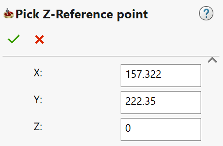
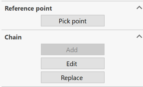
- Click Pick point to pick the reference point. This point defines the level of the section relative to the upper level of the operation.
- The
Pick Z-Reference point dialog box is displayed. Pick the point
on the model and then confirm by clicking the button.
6. Confirm the Section
Geometry dialog box with
the ![]() button.
button.
Editing a Section geometry
You can edit the section or redefine the reference point of the section.
- In the SolidCAM Manager, right-click the section geometry and choose Edit from the menu.
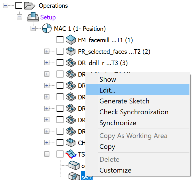
- In the Section Geometry dialog box, click Pick point to pick the reference point again or click Edit/Replace to edit or replace the section chain using the Chain Options dialog box.
- Click the
button to confirm
your changes and close the respective dialog boxes.
Spline Approximation
![]()
This field enables you to define the Spline approximation tolerance for the chain selection.
Related Topics