Geometry
The Geometry tab enables you to define the default values of several Geometry parameters. The Geometry tab contains the following options:
Approximation
Whenever you select a spline edge (NURBS) as a chain geometry for profiles, working areas, etc., the spline will be transformed to lines. The Spline approximation value defines the tolerance that is used when the spline is transformed into lines.
Example:
When you import an IGES surface, the surface boundaries will usually be defined with spline curves. If you mill the outside contour of the surface with a Profile Operation, you have to select the boundary as the profile geometry. If you select a small tolerance, the tool path will show more points on the contour and produce a smoother edge.
Chain selection
The automatic propagation function for chain geometries uses certain tolerances to decide whether two consequent elements are connected or not. The behavior of this function depends on the Gap between the entities.
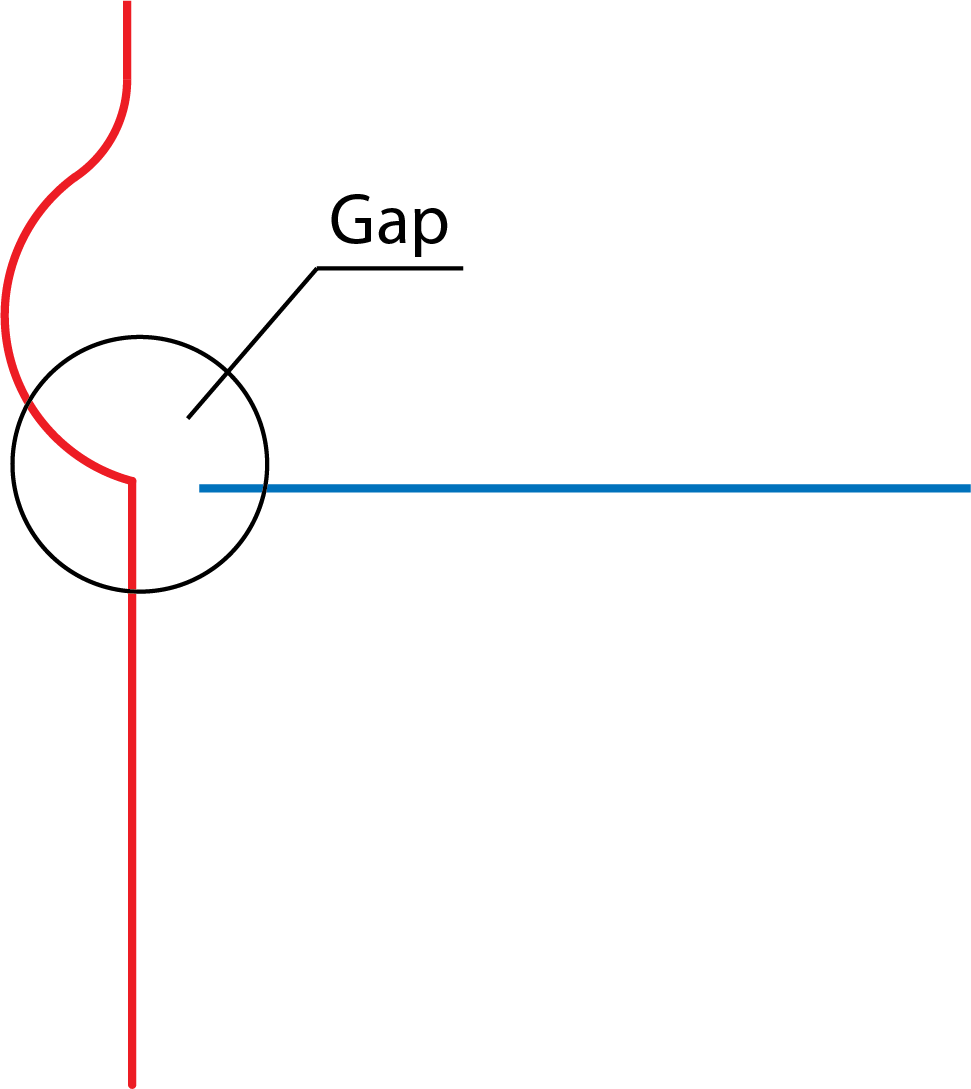
Gap minimum and Gap maximum tolerance
The Curve Propagation feature can function in three different ways:
If the gap between the edges is smaller than the minimum chain gap, the system automatically continues the chain and closes the gap.
If the gap is between the minimum and maximum values, you are asked whether the gap should be closed.
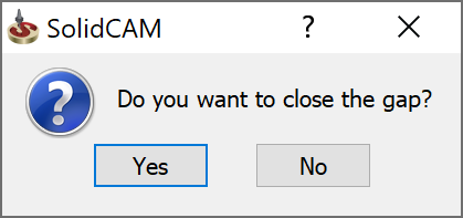
If you answer Yes, the gap is automatically closed.
If the gap is larger than the maximum value for a chain gap, the following message is displayed:
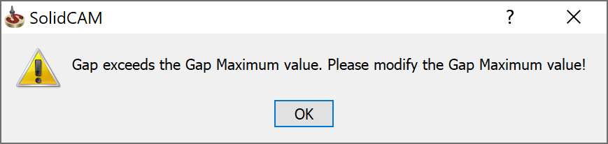
|
These tolerances can be defined separately for each geometry in the Geometry Edit dialog box. |
Show Chain on Work Plane
This option defines the default state of the corresponding option in the Geometry Edit dialog box. When it is selected, all new geometries will show chains projection on the work plane.
Curve
The parameters in the section (Up to Entity, Tangent Propagation, Constant Z propagation, Delta Z Default) define the default state of the corresponding options in the Curve section of the Geometry Edit dialog box. These parameters are set separately for Milling and Turning operations.
Constant-Z Tolerance
When you work in the Constant Z propagation mode, all connected entities on the same Z-level of the current coordinate system will be selected. This tolerance defines the maximum deviation from the Z-plane where an element will still be recognized as being on the same Z-level.
|
The Gap and Constant Z tolerances you should use depend mainly on the size of your geometries and the accuracy of your models or imported 2D/3D files. The default setting can be used for most of the common models, but when you work with very intricate CAM-Parts, for example, a large max. gap tolerance can cause problems as you might close contours in places that should normally be not connected. To avoid this, answer No to the message "Do you want to close the gap?" and switch to single curve mode to make sure you select the correct elements. |
Delta Z Default
This option defines the default state of the corresponding option in the Geometry Edit dialog box. The values set here will be shown when you start editing a geometry.
Smart Face Settings
When you select the check boxes for Pocket/iMachining and Profile, the open edges/walls are automatically detected. Incase, these options are de-selected you can select the Smart Face check box in the Chain section of Geometry Edit dialog box.
Auto-depth
In the Levels page, the Lower level (Depth) value is defined considering the first edge picked during the geometry selection.
If the Take operation depth from first pick on geometry option is cleared, the Lower level value is defined according to the Part lower level.
|
The Auto-depth functionality is used in Face (with profile geometry), Profile, Pocket, and ToolBox operations only. |
Start position shift
This option enables you to customize the choice of the Start position defined in the Modify Geometry dialog box.
When the Shift (% of first edge) option is selected, the start position shifting is defined in percentage of the first edge length according to the specified value.
When the Shift (% of whole chain) option is selected, the start position shifting is defined in percentage of the whole chain according to the specified value.
Colors
This tab enables you to customize the colors used for Geometries in 5Axis/HSS, Gouge check, Swarf Machining, Multiblade Machining, Multi Axis Rough and Port Machining. To change the Geometry color, select the required check box and click the corresponding color button. The standard Windows Color selection dialog box will be displayed, enabling you to pick the desired color.
Geometry type
This tab enables you to define the default Geometry type for Facemill operations. Select Stock based boundary to choose Geometry using existing stock and Part based boundary to define a Geometry.