3D Rough machining
Three strategies are available for rough machining of 3D Models.
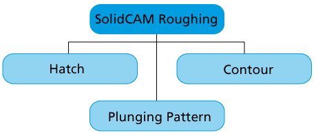
Contour and Hatch strategies perform rough cuts on constant Z-levels that are automatically calculated using the specified values of Lower level, Surface offset and Step down.
Plunging is a totally different concept of removing material from a given pocket, carried out with a special tool. Instead of milling the material, the tool moves up and down as in a drilling motion, travelling along the specified path type.
Choose one of the strategies and specify the additional parameters.
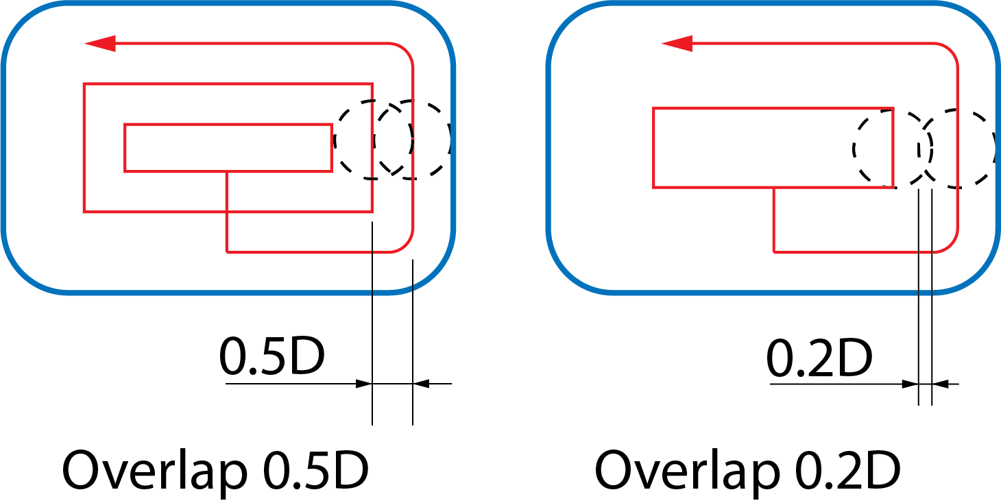
Overlap
Enter the Overlap of adjacent tool passes. The default value is 0.5 (50%).
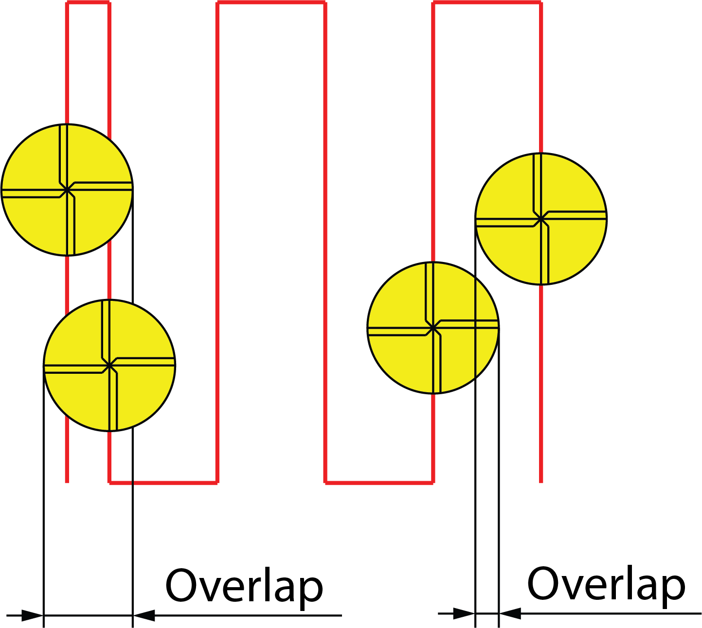
This option enables you to generate the hatch tool path spaced evenly with the automatically calculated Overlap value, which is nearest to the specified Min. Overlap value but not smaller than this value.
When this check box is not selected, the distance between the last pass and the one before it can be smaller than that between all of the other passes.
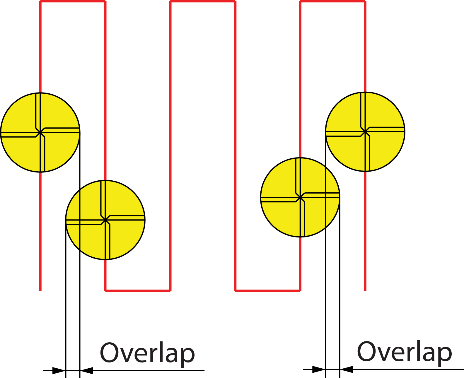
When this check box is selected, the evenly spaced hatch tool path is generated. The overlap between two successive passes is not smaller than the specified Min. Overlap value.
Step down
SolidCAM uses the constant Z pocketing for the roughing. The Step down parameter defines the distance between each two successive Z-levels. Enter the tool's cutting depth.
Clean flat
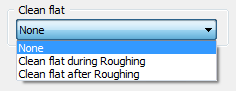
SolidCAM generates a set of Z-levels with equal step down. Sometimes the model ledge with the specified offset falls between the Z-levels defined by Step down and cannot be machined in the current operation.

None
When this option is chosen, the tool machines only at each step down distance. Anything in between is not machined.

Clean flat after roughing
When this option is chosen, the tool performs complete roughing at each step down level and then returns to the flat areas between the step down levels.
Clean flat during roughing
When this option is chosen, SolidCAM produces tool paths at the step down level. At this point, the tool machines the flat area located between the step down levels. After completing the flat area, it goes to the next step down.
Offsets
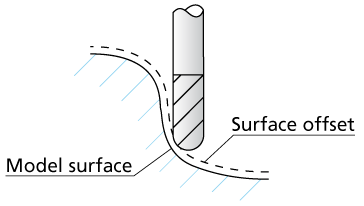
Surface offset is the minimum offset of material in the X-, Y- and Z-direction that remains on the model contour. The value defines the closest distance the tool can get to the model. The rough operation is performed at constant Z-levels.
In addition to the specified Surface offset, the roughed model shows stairs of rest material with a height equal to the Step down value. To obtain a uniform offset on the model, a semi-finish operation should be executed.
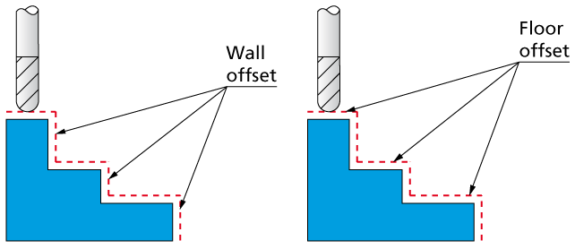
In 3D Milling of prismatic parts, you often need to use different offset values for vertical and horizontal areas. With the Wall offset value, you can define the XY-offset of any surface that is not absolutely flat. To define the Z-offset to the absolute horizontal (flat) surfaces, use the Floor offset parameter.
Z-Entry
This option enables you to control how the tool plunges into the material. click the button to display the Z-Entry dialog box.
Mode
With this option, SolidCAM locates open pocket areas and enables you to machine them with a specific strategy. This strategy enables you to combine pocket and profile tool paths in order to provide the best productivity in open pocket machining.
Use the Wall and Flat offsets for 3D machining of prismatic parts. In 3D Milling of
non-prismatic parts, it is best to use surface offset and not Floor and Wall offsets. Set the Wall and Flat offsets to 0 and enter the desired value of the Surface offset.
Fillet size for last cut
This option enables you to add a radius to a sharp corners of the tool path without having to change the geometry.
More...
Complete Z-Level
This option enables you to define the order of the machining Z-levels.
More...
Vertical Wall with fillets
This option enables special handling of vertical walls with fillets between them in a prismatic part.
More...
Rest Material
With the 3D Roughing strategy, SolidCAM generates a number of sections parallel to the XY-plane of the CAM-Part Coordinate System. These sections are generated with a Z-step defined either by constant step down or by scallop. In each of these sections SolidCAM uses the section profile geometry to produce a pocket tool path. The Rest material feature enables SolidCAM to machine in each of these sections only in areas where the previous tool was not able to machine.
Rest Material for Roughing