Shape Type
Different components (e.g., Cutter vs. Holder) offer different Shape type options, which determine how you want to specify its geometry. By default, the Shape type is set to Parameter data.
Parameter Data
A Cutter component, for example, can be defined by its dimensions using the Parameter Data pictured in the image.
Refer Tool Parameters for details of the individual parameters.

Sketch (2D)
A Cutter component, for example, can also be defined via a 2D Sketch as shown below.
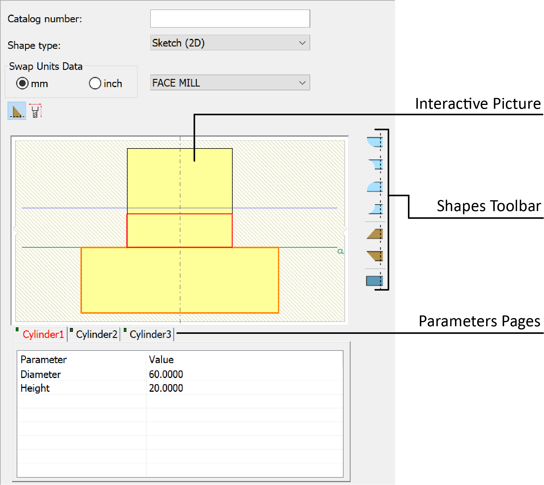
Using the Sketch (2D) option, the Cutter component is defined by segment shapes such as cylinders, cones and toruses.
Shapes can be added using the Shapes Toolbar
![]()
or the interactive picture right-click commands

The actual dimensions can be edited by selecting the segments on the interactive picture and by using the corresponding Parameters pages. You can add shapes using the interactive picture right-click commands or the Shapes Toolbar.
Select the holder's element on the picture or through the parameter pages.
Enter the new value of the parameter.
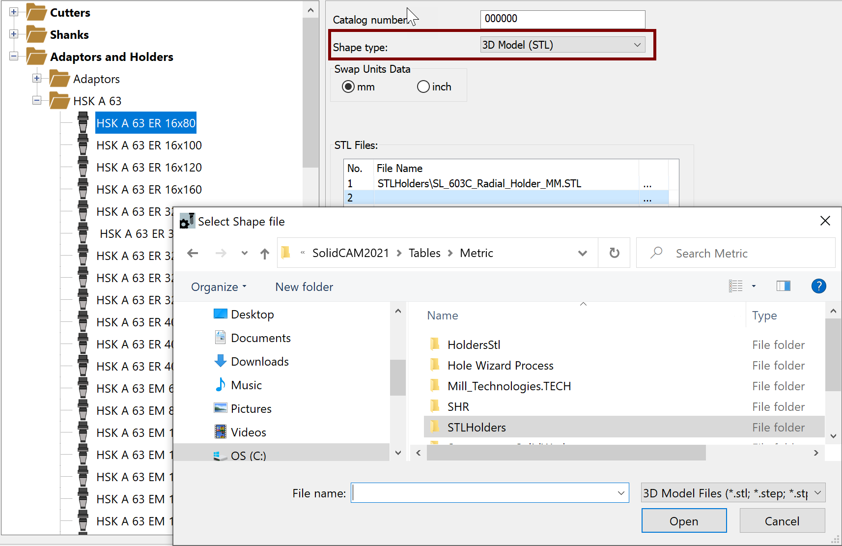
3D Model (STL)
Clicking the ![]() button displays
the Select Shape file dialog box,
where you can browse for, select and Open the STL/STEP file of your choosing.
Each row in the STL Files table enables you to define an additional file.
button displays
the Select Shape file dialog box,
where you can browse for, select and Open the STL/STEP file of your choosing.
Each row in the STL Files table enables you to define an additional file.
|
To simplify your selections, default Shape types are set for the components as follows:
|
Related Topics